Electrical Submersible Pump Workover by Using Intermediate Completion Design
In the field named “X” (for confidential reasons), there are electrical submersible pumps (ESPs) used in wells to produce at very high flow rates. The goal of this paper is to propose a completion design that enables the mechanical isolation of fluids produced from the reservoir while performing the ESP workover. The data are the reservoir properties and well architecture. To achieve this objective, it is necessary to select the materials, to choose the working pressures and temperatures, to choose the appropriate completion method, to draw the completion schematic with PowerDraw software and to write the running procedures. The obtained results are hydrogenated nitrile as suitable elastomers for the sealing elements, carbon steel as metallurgy, working pressure of 1100 psi and temperature of 110°C. The intermediate completion is found to be appropriate completion design. The intermediate completion design is used in the field X for the existing wells having at least casing size 7 inches, and for those having 9-5/8 inches, the Y-tool design is used.
Introduction
One hundred years ago, the oil and gas industry produced resources from wells using the reservoir’s natural energy [1]. But after some time, notice was done that the removal of fluids from the underground reservoir reduced the bottom hole flowing pressure ; hence the reservoir’s energy was not more sufficient to drive the hydrocarbons to the surface [2, 3, 4]. Therefore, the necessity to employe an activation method which will enable an increase in the production rate.
Several artificial lift methods have been adopted in literature to increase the flow rate such as progressing cavity pump, sucker rod pump, electrical submersible pumps and gas lift [5, 6, 7, 8]. However, ESP units have proved to be one of the most commonly used activation methods in lifting a much higher liquid rate than the other methods and found their best use in high on- and offshore applications. It is believed that today approximately 10% of the world’s oil supply is produced with ESP installations [9, 10, 11, 12].
ESP is an artificial lift method easy to install and operate, which uses a submerged electrical motor driving a multistage centrifugal pump through a shaft. This pump enables the recovery of high liquid volumes [13, 14, 15]. After some years of production, the depleted reservoir starts producing abrasive particles such as sand and scales, which will reduce productivity and later cause pump failure [16, 17, 18]. Hence the need to change this pump preventing hydrocarbons from reaching the surface, which is very dangerous for the environment and the personnel on-site. To replace this pump, well killing must be made, but it is generally challenging to restart production after this [19, 20]. Majority of wells making use of an ESP face this problem. A central question emerges from this observation: Is it possible to mechanically isolate fluids produced from the reservoir, while performing the ESP workover?
This paper aims to propose an appropriate completion design that enables the mechanical isolation of fluids produced from the reservoir while performing the ESP workover in a field X. To achieve this paper, the following tasks will be performed: to choose the appropriate materials which are elastomers and metallurgy, to determine the working pressures and temperatures ; to select the appropriate and economical completion design ; to draw the completion schematic, and to write the installation procedures. The above objectives are achieved by using the technical and economic approaches. The present paper has three sections : The introduction is given in this section. Section 2 presents the data, tools, the proposed completion design, the completion method used, the selected materials, the completion schematic and the running procedures. The last section presents the conclusion.
Data, Methods and Results
The data used to design the completion is presented in Table 1.
| Reservoir data | Pressure = 1000 psi |
|---|---|
| Temperature =100°C | |
| Oil API gravity = 38 | |
| CO content= 0.5mole% ; H S 2 2 content= 10 ppm | |
| Well data | TVD (MD) =3000 m |
| Vertical well ( no inclination) | |
| Workover objectives | Formation isolation without killing the well |
| ESP change-out |
Table 1: Well completion design data.
The field X consists of a vertical well as depicted in Figure 1.
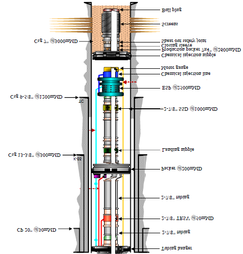
In Figure 1, the well profile starts with a 20” conductor pipe (CP) hammered till 30 mMD, followed by three casings (13-3/8” surface casing with casing shoe at 300 mMD of grade K55; 9-5/8” intermediate casing with casing shoe at 1200mMD of grade N80 and a last 7” production casing at 3000 mMD of grade L80 with a nominal weight of 23 pounds per foot). The upper completion is 2-7/8” with a Tubing Retrievable Safety Valve (TRSV) to control the well at 50 mMD, a Hydro II packer at 200 mMD, a sliding sleeve door (SSD) to allow for slickline operations at 1000mMD, an ESP to increase the production rate at 2500 mMD and a 7x4” production packer at 2600 mMD. Table 2 presents the primary data needed for the completion design.
| Reservoir data | Temperature =100°C |
|---|---|
| Pressure = 1000 psi | |
| Oil API gravity = 38 | |
| CO content= 0.5 mole % ; H S 2 2 content= 10 ppm | |
| Well Data | TVD (MD) =3000 m |
| Vertical well ( no inclination) | |
| Workover objectives | Reservoir fluids isolation without well killing |
| ESP change-out |
Table 2: Basic data needed for the completion design.
As presented in Table 2, the primary data required for a completion design are reservoir data, which takes into account pressure, temperature, fluids specific gravity and its composition, well data such as the measured depth.
Material selection, completion method selection and economic analysis
The appropriate elastomer used in the sealing elements is hydrogenated nitrile (HNBR) with the partial pressure of CO2 equals to 0.34 atm and H2S of 0.0068 atm. The recommended metallurgy for the completion design is carbon steel. The working pressures and temperatures of the selected equipment are 1100 psi and 110°C, respectively. It is well known that the two completion designs used techniques to mechanically isolate the fluid produced from the reservoir while performing the EPS workover are the intermediate completion design and Y-tool design [21, 22, 23, 24]. In this case, the appropriate completion method is the intermediate completion design. Based on an economic analysis, the equipment and operation costs for both designs are considered in the following paragraph.
The equipment cost evaluation for intermediate completion design is seen in Table 3.
| Equipment | Cost ($)/unit | Unit | Cost($) |
|---|---|---|---|
| Shifting tool | 4,000 | 1 | 4,000 |
| Packer | 22,000 | 1 | 22,000 |
| Extension | 2,000 | 2 | 4,000 |
| Ball valve | 80,000 | 1 | 80,000 |
| Total cost ($) | / | / | 110,000 |
Table 3: Equipment cost for intermediate completion design. The equipment cost evaluation of Y-tool design is seen in Table 4.
| Equipment | Cost ($)/Unit | Unit | Cost ($) |
|---|---|---|---|
| Y-tool | 5,000 | 1 | 5,000 |
| Closing nipple | 400 | 1 | 400 |
| Total cost($) | / | / | 5,400 |
Table 4: Equipment cost for Y-tool design.
Tables 3 and 4 present a difference of 104,600$. The kick-over tool is the most economical, which could be chosen. it is still required slickline intervention for plug setting and removal that needs to be considered in the evaluation too. The operation cost of each method appears in the Tables 5 and 6.
| Cost ($)/Day | Number of days | Cost ($) | |
|---|---|---|---|
| Completion personnel (2) | 1,500 | 6 | 9,000 |
| Completion personnel (2) | 1,200 | 6 | 7,200 |
| Used rig time | 40,000 | 3 | 120,000 |
| Intervention (No) | / | / | / |
| Total cost ($) | / | / | 136,200 |
Table 5: Operation costs for intermediate completion design.
| Cost ($)/Day | Number of days | Cost ($) | |
|---|---|---|---|
| Completion personnel (2) | 1,500 | 5 | 7,500 |
| Completion personnel (2) | 1,200 | 5 | 6,000 |
| Workover personnel (2) | 1,600 | 5 | 8,000 |
| Workover personnel (2) | 1,300 | 5 | 6,500 |
| Used rig time | 40,000 | 2 | 80,000 |
| Intervention (Yes) | 8,000 | 5 | 40,000 |
| Total($) | / | / | 148,000 |
Table 6: Operation costs for Y-tool design.
Tables 5 and 6, the overall cost, which is the sum of the equipment cost and operation cost for the intermediate completion design is 246,200 $, and that of the Y-tool design is 153,400 $. Hence the Y-tool design is the economical design that enables the formation isolation without killing the well, but it will not be used here due to its unavailability. With the last casing size 7 inches, there is no kick-over tool size available to fit in since its minimum outside diameter is
8-1/2 inches. This design is used in a well with last casing size 9-5/8 inches or else constrained to use the intermediate completion.
Well schematic and running procedure
The proposed well completion design is depicted in Figure 2.
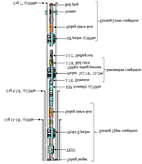
Figure 2 is made of the shifting tool and the intermediate completion for the ESP workover. It comprises one isolation packer, two extensions, and one ball valve as shown in Figure 3.
(b) (a) (c) (d) Figure 3: (a) Shifting tool, (b) isolation packer, (c) extension and (d) ball valve.
The completion running process is done in five steps as shown in Figure 4.
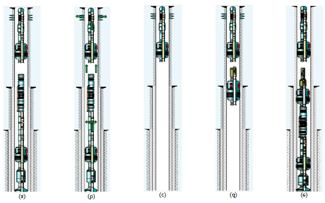
The first step is to open the SSD with the slickline assembly because, due to the pump damage, the kill fluid will not be able to pass from the surface through the well down the reservoir. It consists of lowering on a thin cable, a shifting tool that will help open the SSD (Figure 4a), which is a completion component that allows communication between the tubing and the annulus. The next step is killing the well. This is done by pumping a kill fluid, fluid with a density higher than the reservoir fluid density, from the surface with pressure lower than the formation fracture pressure, till down the well (Figure 4b) where it will push the hydrocarbons back into the reservoir preventing production. The next step is POOH the upper completion with the damaged ESP assembly (Figure 4c). A safety barrier must be present throughout the workover operation considering well control. The christmas tree will be pulled, and the blow out preventer (BOP) installed. The next step is to RIH
the intermediate completion (that is, the isolation packer, extensions, and ball valve) as shown in Figure 4d. The tubing string, the ESP assembly, together with the shifting tool are assembled at the surface and then reinstalled into the well (Figure 4e). At the end of this replacement, the BOP is then POOH, and the christmas tree is reinstalled back. After this last step, production restarts.
Conclusion
The objective of this paper was to propose a feasible completion design that enables the mechanical isolation of fluids produced from the reservoir while performing the electrical submersible pump workover. It was found that the best material to be used is carbon steel for the metallurgy and hydrogenated nitrile as elastomers. Carbon steel is preferred since it is found in an environment of high temperature (212°F), low CO2 content (0.5 mole %), and H2S content 10 ppm. For the sealing elements, nitrile could be used in the presence of the produced fluid, completion fluid, and well kill fluid. Still, the operating temperature is too close to its upper limit applications, and it considers less than 10 ppm hydrogen sulfide, but it is 10 ppm. Hence hydrogenated nitrile is the appropriate elastomer for these conditions. The appropriate completion method is the intermediate completion design. It comprises one packer that isolates the annulus between the casing and the tubing string. Two extensions that account for spacing out, one ball valve which enables without well-killing formation isolation, and workover operations safely and a shifting tool that allows the opening and closure of the ball valve. This case was a typical case where the intermediate completion was the best because of the unavailability of a kick-over tool to fit in the last 7 inch casing size since it has a minimum outside diameter of 8-1/2 inches hence can only be used in wells with last casing size 9-5/8 inches or more.
References
-
Economides M, Hill D, Zhu D, Elig-Economides C (2013) Petroleum Production Systems. In : 2nd (Edn.), Prentice- hall, Westford, USA.
-
Katz D, Barlow W (1995) Relation of Bottom-Hole Pressure to Production Control. American Petroleum Institute, New York.
-
John R, Richard L (2017) Introduction to petroleum engineering. Wiley, New Jersey, pp: 344.
-
Alain M (2014) Geology and Geodynamics of Hydrocarbons, Encyclopedia of Energy 5: 11-15.
-
Boyun G, William L, Ali G (2007) Petroleum Production Engineering, a computer-assisted approach. In : 1st (Edn.), Elsevier, Oxford.
-
Guo B, Lyons WC, Ghalambor A (2007) Petroleum Production engineering a computer Assisted Approch. ES Books, pp: 309.
-
John R, Richard L (2017) Introduction to petroleum engineering. Wiley, New Jersey.
-
Hernandez A (2016) Fundamentals of Gas Lift Engineering: Well design and Troubleshooting. Elsevier.
-
Gabor T (2009) Electrical submersible pumps manual, Designs, Operations, and Maintenance. In : 1st (Edn.), Elsevier, Burlington.
-
Gabor T (2018) Electrical Submersible Pumps Manual, Design, Operations, and Maintenance. In : 2nd (Edn.), Elsevier, Cambridge.
-
Kamga NRM, Dongmo ED, Nitcheu M, Matateyou JF, Kuiatse G, et al. (2022) Production step-up of an oil well through nodal analysis, Journal of engineering, pp: 1-8.
-
Belomo V, Nitcheu M, Dongmo ED, Njeudjang K, Kuiatse G, et al. (2022) Activation of a non-erruptive well by using an electric submersible pump to optimise production. Petrovietnam Journal 6: 36-42.
-
Matanovic D, Cikes M, Moslavac B (2012) Sand control in well construction and operation. Springer, Environmental Science and Engineering, pp: 1-11.
-
Renpu W (2011) Advanced Well Completion Engineering. In : 3rd (Edn.), Elsevier, Oxford, pp: 737.
-
Rigtrain D (2006) Well Services Training; Well kill principles and procedures. Houston.
-
Crumpton H (2018) Well control for completions and interventions. In : 1st (Edn.), Elsevier, Oxford.
-
Aminzadeh F (2009) Hydraulic fracturing and well stimulation. 1st (Edn.), Jon Wiley & Sons, Hoboken.
-
Bellarby J (2009) Well completion design. Elsevier, Amsterdam.
-
Economides M, Nolte K (2000) Reservoir Stimulation. 3rd (Edn.), John Wiley & Sons, UK.
-
King G (1998) An Introduction to the basics of well completions, stimulations, and workovers. In : 1st (Edn.), Georges E King, Tulsa.
-
Schlumberger (2012) Kickover Tools; Slickline service tools for installing and retrieving devices in all orienting- style side pocket mandrel. Schlumberger, Houston.
-
Montrose R (2002) Completion Design Manual. In: 1st (Edn.), Aberdeen.
-
Lee JH, Lee MH, Jang GH (2013) Effect of an Hourglass- Shape Tapered Sleeve on the Performance of the Fluid Dynamic Bearings of a HDD Spindle Motor. Information Storage and Processing Systems.
-
Alali EA, Bataweel MA, Urbina EAR, Bulekbay A (2020) Critical Review of Multistage Fracturing Completions and Stimulation Methods. Abu Dhabi International Petroleum Exhibition & Conference, pp: SPE-203284- MS.
- Lessons to Learn: Trees are More than the Lungs of the World
- Community Forestry Enterprises as a Model for Sustainable Forest Development: The Case Of The "Baja Tarahumara" in Chihuahua, Mexico
- Ecological and Socio-Economic Impacts of Chromolaena odorata and Mesosphaerum suaveolens, Two Invasive Alien Species in Central and Southern Benin, West Africa
- Epigenetic Sustainability: Modeling the Human Factor as a Natural Resource through Science 4.0 and the NR3C1 Biological Pilot
- Growth-at-Risk: A Framework for Assessing Economic Vulnerability
- The Rural Territory as a Socioecological System for the Management of Public Policy for Sustainable Rural Development