Subtrochanteric Fracture after Cannulated Screw Fixation of Femoral Neck Fractures: Biomechanical Analysis and Case Series
Objectives: To determine whether a condensed screw construct or a dispersed screw construct is more likely to sustain a subtrochanteric fracture after cannulated screw fixation for femoral neck fractures, and to report the characteristics of the screw constructs in our patient population that sustained a subtrochanteric fracture. Methods: We performed a biomechanical analysis of two screw constructs and a consecutive case series of patients treated with cannulated screw fixation for femoral neck fractures sustaining subtrochanteric fracture. The biomechanical study consisted of two groups of biocomposite femora: (1) Condensed screw group (CS) (n=7); (2) Dispersed screw group (DS) (n=7). Axial loading was applied to the biomechanical group until fracture, and a load deformation curve was used to quantify the mechanical behavior by measuring the load (kN) at failure, displacement (mm) at failure, and initial construct stiffness (kN/mm). The case series involved a retrospective chart review of patients treated with cannulated screw fixation who sustained a subtrochanteric fracture (n=7). Radiographs were analyzed for trends in failure during chart review. Results: There was a trend towards increased load to failure in the DS group compared with the CS group. We did not observe a statistical difference (p = 0.1023) in load to failure, but we did observe increased stiffness in the DS group (p = 0.0346). Post-hoc non-inferiority analysis demonstrated that the DS were not inferior to CS group. We found a 3.9% incidence of periimplant fracture in our patient population who underwent cannulated screw fixation. Conclusion: The results of this study suggest that maximally dispersing screw placement within the femoral neck, may have higher load to failure than more condense screws. The authors of this study advocate maximizing spacing of the screws within the femoral neck while letting the anatomy of the femoral neck dictate the position of the distal screw relative to the lesser trochanter.
Introduction
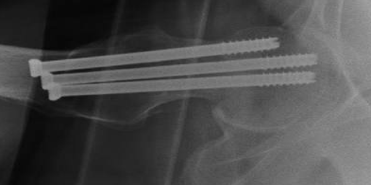
Peri-implant subtrochanteric femur fracture is a known complication following cannulated screw fixation of femoral neck fractures (Figure 1a-1c) [1, 2, 3, 4]. Although this is a relatively rare post-operative event, with reported incidence ranging from 0.78-5.7%, it has been a topic of discussion in the literature over the past couple of decades [1, 2, 5, 6]. Although the literature has confirmed screw fixation with a triangular configuration, a displaced fracture, and poor reduction as risk factors for nonunion in femoral neck fractures treated with cannulated screws, controversy persists regarding the risk factors for subtrochanteric femur fracture after cannulated
screw fixation [7, 8]. Previous authors have suggested that the distal-most screw should not be placed below the inferior border of the lesser trochanter (LT) in order to minimize the risk of subtrochanteric fracture. Kloen P, et al. [1] have suggested that screws placed too close together and violation of the lateral cortex with multiple passes may increase the incidence of subtrochanteric fracture [1, 9, 10].
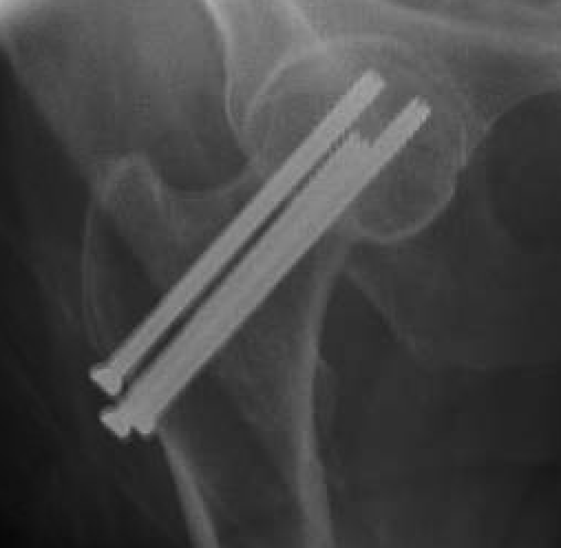
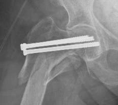
(a) (b) (c) Figure 1: (a) AP and (b) lateral radiographs show placement of cannulated screw prior to fractures. (c) AP radiographs demonstrates post-operative subtrochanteric fracture that occurred 5 years later.
At our institution we believe that screw dispersion is the most significant protective variable to decrease subtrochanteric fracture incidence. We have successfully treated Garden I and II femoral neck fracture with the distal screw placed below the LT when the patient’s anatomy required it to maximize screw dispersion. The purpose of this study was two-fold. First, to determine whether a dispersed screw (DS) construct is stronger than a condensed screw (CS) construct. Second, to report the incidence of these injuries and the characteristics of the constructs in our population that sustained a peri-implant subtrochanteric femur fracture. Our hypothesis was that DS construct would require a greater load to failure than a CS construct.
Material and Methods
Biomechanical Arm
Specimen Preparation: We utilized fourteen, left-sided fourth generation synthetic composite femora (model #3403 Sawbones, Pacific Labs, Vashon, WA) for this study. These models have demonstrated similar structural properties to natural human bones, but with significantly lower variability possibly making them better testing subjects than cadaveric bone [11, 12, 13]. In our case series, the majority (57%) of peri- implant subtrochanteric femur fracture were late fractures, meaning fracture healing had already occurred at the time of subtrochanteric fracture. The mean post-operative day was 668 ± 948 days and the median post-operative day was
152.5 (range 4 to 2345 days after fixation). Therefore, the decision was made to not osteotomize the femoral necks of our specimens to simulate a healed fracture, which is comparable to how other studies have chosen to analyze their specimens [14].
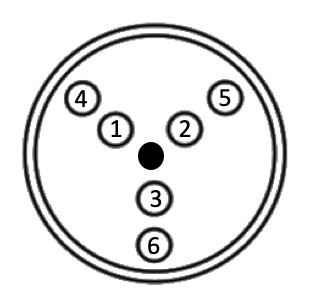
Fourteen femurs were evenly divided into two screw spacing construct groups: (1) Condensed screw (CS) group; (2) Dispersed screw (DS) group. In order to assure comparable screw placement, we utilized a fixed triangle guide (Asnis III set, Stryker, Mahwah, NJ) for the placement of the guide pins into the femora. Under fluoroscopy, the guide pins were placed centered along the anatomic axis of the femoral neck by placing the triangular guide along the lateral cortex of each femora. Each specimen comes manufactured with a hole in the lateral cortex in the center of the femoral neck that the guide spike was placed into for reproducible centering in each specimen (represented by the black dot in Figure 2).
In the CS group, we placed three 3.2 mm guide pins in holes numbers 1, 2, and 3 in a “regular V” or “inverted triangle” construct, which has been shown to be the most biomechanically stable construct [15]. The guide pins were advanced to subchondral bone, the lengths measured, and then 5 mm was subtracted from each pin. The appropriate lengths of standard stainless steel 6.5 mm cannulated 20 mm partial threaded screws (Asnis III, Stryker, Mahwah, NJ) were utilized for fixation (each at 90 mm in length) (Figure 3a&b).
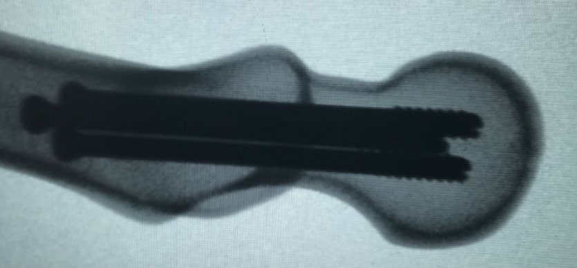
(a) (b) Figure 3: Condensed screw fluoroscopic images with fracture through the subtrochanteric region of the femur. (b) AP and (b) Lateral.
In the DS group, we systematically placed the screws into the guide to maximize screw spread within the femoral neck. This was accomplished by first placing a 3.2 mm guide pin into holes numbers 5 and 6 with the triangular guide spike in the manufacturers center hole (Figure 2). Next, a 3.2 mm guide pin was placed into the center hole (black dot in Figure 2) and the guide was placed over this guide pin into hole number 3, which shifted the entire guide system cranially. We then placed our final 3.2 mm guide pin into hole number
4, which maximized screw dispersing in these samples. As in the CS group, the guide pins were advanced to subchondral bone, the lengths measured, and then 5 mm was subtracted from each pin. The appropriate lengths of standard stainless steel 6.5 mm cannulated 20 mm partial threaded screws (Asnis III, Stryker, Mahwah, NJ) were utilized for fixation (distal-95 mm; anterior–85 mm; posterior 90 mm) (Figure 4).
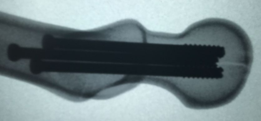
(a) (b) Figure 4: Dispersed screw fluoroscopic images with fracture through the subtrochanteric region of the femur. (a) AP and (b) Lateral.
The distal half of the femora from both groups were then osteotomized and discarded to facilitate fixation for further testing. Each proximal specimen was then potted distally in a 2-part epoxy mold (Bondo, 3M Company, Atlanta, GA) allowing to completely dry (Figures 5&6). Fluoroscopic images were then obtained of each specimen to ensure satisfactory placement.
Biomechanical Testing
Biomechanical tests were initially conducted at Temple Bioscience Health District (Temple, TX) using an Instron 8874 System linear torsion dynamic test system (Instron Model E10000, Norwood, MA). Each specimen was placed into a titanium jig distally and positioned in 25-degrees of adduction to simulate single leg stance [16, 17]. A custom molded stainless-steel cup that simulated the acetabulum was used for proximal fixation and attached to a load cell on the Instron machine (Figure 5). A 100 Newtons (N) preload was applied to the femoral head to remove any slack from the system, and the femoral head was then compressed at a rate of 1 mm/min until gross mechanical failure was achieved or the machine reached its maximal load. This machine successfully fractured two samples, but was then unsuccessful in fracturing the third sample, at which point further testing was ceased.
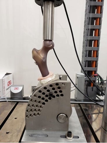
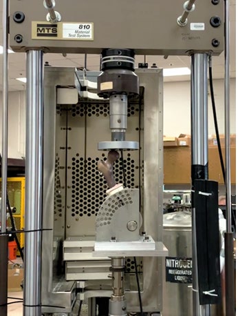
Due to concerns with fracturing all samples, we located a machine with a larger maximal load cell. Testing was resumed with a 20 KIP Axial Force MTS 793 load frame at Texas A&M (Bryan-College Station, TX), which has significantly greater compressive force for the remaining 12 samples. Custom adapters were designed and machined for use with the fixtures that were used with the previous Instron machine. Each specimen was placed into a titanium jig distally and positioned in 25-degrees of adduction (Figure 6). A 100 N preload was applied to the femoral head to remove any slack from the system, and the femoral head was then compressed at a rate of 1 mm/min until gross mechanical failure was achieved, as defined by a sudden drop in load that was confirmed by visual assessment of gross failure or cracking. Throughout this process, displacements (mm) and loads (kN) were measured at a rate of 100Hz and recorded.
Each mechanical test produced a load deformation curve that was then used to quantify the mechanical behavior by measuring the load (kN) at failure, displacement (mm) at failure, and initial construct stiffness (kN/mm). Load to failure was calculated by identifying rapid decline in the load present on the load deformation curve and correlating those drops with visually observed gross failure and cracking. Once the failure point was identified, the corresponding load and displacement values were extracted from the load displacement curve. Stiffness was calculated as a linear regression of the load deformation curve from 0 to 0.5 mm of deflection.
Clinical Data
After approval was obtained from our Institutional Review Board (IRB) all patients with femoral neck fractures treated with CRPP (n= 1407, CTP code 27235) between January 1997 and July 2018 were reviewed. The presence of a peri-implant subtrochanteric femur fracture, time of fracture from operative date, patient age, patient sex, laterality, Garden classification, and multiple screw construct characteristics, which are discussed below, were recorded for each patient. A total of 229 patients were treated with cannulated screws for femoral neck fractures during our study timeframe. Of those, nine patients (3.9%) sustained a peri-implant subtrochanteric fracture, which is comparable to reported incidence in the literature [1, 2, 5, 6]. Two of the patient’s X-rays were incomplete, allowing us 7 patients for evaluation. We reviewed initial injury films, post-operative films after CRPP, post-injury films after subtrochanteric femur fracture, and post-operative revision films. All films were evaluated by an upper level resident and then validated by a fellowship trained orthopaedic trauma surgeon.
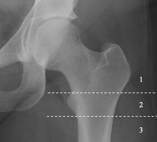
We described the location of the distal screw by categorizing each patient’s construct into one of three categories (Figure 7): (1) Above the superior border of the LT; (2) Within the margins of the superior and inferior borders of the LT; (3) Below the inferior border of the LT. Additionally, we described the screw disbursement by classifying each construct as either divergent, parallel, or convergent. We further described the screws spacing as condensed, dispersed, or laterally condensed-medially dispersed.
Statistical Methods
We used descriptive statistics to describe the sample characteristics, and frequencies and percentages to describe categorical variables. We used a two-sample t-test to assess differences in failure displacement, failure load, and stiffness between concentrated screw placement and dispersed screw placement. Statistical significance was set at <0.05. Post-hoc analysis for non-inferiority was then utilized to compart the same three variables between the groups.
Results
Biomechanical Results
Fourteen femora in total, seven CS constructs and seven DS constructs, were axially loaded to failure. All specimens failed through the subtrochanteric region (Figures 3 and 4). Two femora, one from each screw construct sample, were tested on the initial Instron machine and twelve femora, six in each screw construct sample, were tested on the more powerful machine. Individual sample testing results are presented in Table 1. For the purposes of analysis, we analyzed the twelve femora in isolation (main sample) initially due to differences in machine calibration and then analyzed all fourteen femora (combined sample) for comparison.
| ID | Failure Displacement (mm) | Failure Load (kN) | Stiffness (kN/mm) | Screw Construct |
|---|---|---|---|---|
| 1A* | 2.442 | 6.372 | 1.114 | Concentrated |
| 1B | 4.861 | 8.099 | 1.323 | Concentrated |
| 1C | 3.273 | 7.187 | 1.622 | Concentrated |
| 1D | 4.557 | 8.77 | 1.351 | Concentrated |
| 1E | 4.447 | 8.114 | 1.589 | Concentrated |
| 1F | 4.399 | 9.491 | 1.629 | Concentrated |
| 1G | 2.677 | 7.16 | 2.525 | Concentrated |
| 2A* | 3.675 | 9.707 | 1.335 | Dispersed |
| 2B | 3.566 | 8.697 | 2.788 | Dispersed |
| 2C | 5.249 | 9.943 | 1.971 | Dispersed |
| 2D | 3.441 | 7.513 | 2.373 | Dispersed |
| 2E | 2.693 | 7.039 | 2.497 | Dispersed |
| 2F | 4.606 | 9.633 | 2.171 | Dispersed |
| 2G | 6.489 | 10.74 | 2.092 | Dispersed |
| *Sample tested on initial Instron machine. |
Table 1: Biomechanical Arm-Testing Results.
The DS construct trends towards a greater load displacement and load to failure compared with the CS construct (Figure 8a-d), but in statistical analysis we did not observe a difference in failure load (Table 2). However, in post-hoc non-inferiority analysis, the DS construct was not inferior to the CS in load to failure. The post-hoc non- inferiority analysis assumed a noninferior margin ratio of 1.05 (disperse/concentrated); a significant result was not detected (p=0.8526). The mean failure load (kN) in the main sample (N=12) was 8.14 ± 0.90 and 8.93 ± 1.44 (p=0.2824) in the CS group and DS group, respectfully. In the combined sample (N=14) the mean failure load (kN) was 7.88 ± 1.06 and 9.04 ± 1.35 (p = 0.1023) in the CS group and DS group, respectfully. With regard to construct stiffness, the DS group demonstrated a greater stiffness in both the main sample (p = 0.0163) and the combined sample (p = 0.0346).
| Failure Displacement (mm) Mean (SD) | Failure load (kN) Mean (SD) | Stiffness (mm/kN) Mean (SD) | |
|---|---|---|---|
| COMBINED SAMPLES | |||
| Concentrated Screws (N = 7) | 3.81 (0.99) | 7.88 (1.06) | 1.59 (0.45) |
| Dispersed Screws (N = 7) | 4.25 (1.29) | 9.04 (1.35) | 2.18 (0.46) |
| P-value | 0.4911 | 0.1023 | 0.0346 |
| MAIN SAMPLE | |||
| Concentrated Screws (N = 6) | 4.04 (0.86) | 8.14 (0.90) | 1.67 (0.44) |
| Dispersed Screws (N = 6) | 4.34 (1.39) | 8.93 (1.44) | 2.32 (0.30) |
| P-value | 0.6588 | 0.2824 | 0.0163 |
Table 2: Biomechanical Arm-Testing Processed Data.
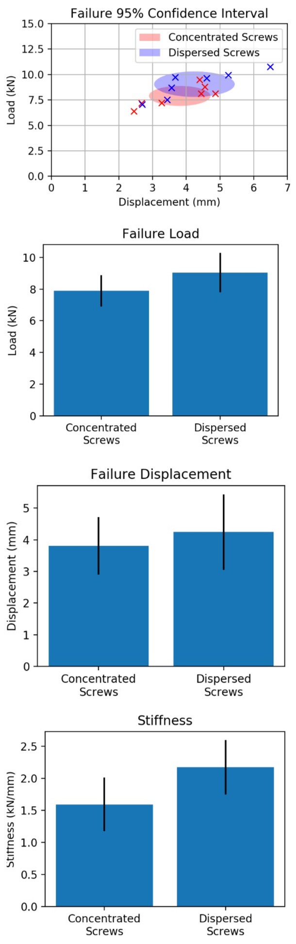
Figure 8a: Failure 95% confidence interval.
Figure 8b: Failure Displacement.
Figure 8c: Failure Load.
Figure 8d: Stiffness.
Clinical Results
Nine patients (3.9%) were treated with cannulated screw fixation subsequently sustained a peri-implant subtrochanteric femur fracture. Patient demographics and baseline data are presented in table 3. Seven patients had complete X-rays sets available and were assessed in the final analysis (Table 3). Each of the seven patients were treated with 6.5 mm cannulated screws. The median age at time of peri-implant fracture was 77 (range, 70-90). There were three males and four females. There were four left-sided fractures and three right-sided fractures (Table 4). Three of the initial fractures were classified as Garden 1 fractures, two as Garden 2 fractures, and two as Garden 3 fractures.
Five patients (71%) were treated with an inverted triangle constructs, 1 patient (14%) was treated with a standard triangle construct, and 1 patient (14%) was treated with a 2-screw construct. The distal screw was proximal to the superior border of the LT in 2 patients (29%), within the margins of the superior and inferior borders of the LT in 4 patients (57%), and distal to the inferior border of the LT in 1 patient (14%). In four of the femurs (57%) the screws were divergent, in 1 femur (14%) the screws were parallel, and in 2 femurs (29%) the screws were convergent. We further classified these relationships-4 femurs with condensed screws, 2 femurs with dispersed screws, and 1 femur with screws that were laterally condensed-medially dispersed.
At the lateral margin of the femur there were 4 screw constructs (57%) that had screw disbursement ≤1 screw diameter and 3 screw constructs (43%) that had screw disbursement ≤2 screw diameters relative to each other. There were no screw disbursements at the lateral margin in the third or fourth category. At the tips of screws there were 2 screw constructs (28%) that were ≤1 screw diameter relative to each other, 2 screw constructs (28%) that were ≤2 screw diameters relative to each other, 1 screw construct (14%) that was ≤3 screw diameters relative to each other, and 2 screw constructs (28%) that were >3 screw diameters relative to each other.
Status-post fracture, five of the patients (71%) were treated with a cephalomedullary device, 1 patient was treated with a hip screw and side plate (14%), and 1 patient with hemiarthroplasty (14%). One patient was later revised to the total hip arthroplasty. None of the patients used tobacco at the time of injury and none of the patients had any significant post-operative complications. All of the patients were functional ambulators prior to their injuries. One patient had a history of metastatic prostate cancer, but there was no evidence that this was a pathologic fracture, so the patient was included in this case series.
| Total (N=7) | |
|---|---|
| Age* | 77 (70-90) |
| Sex | |
| Male | 3 (42.9%) |
| Female | 4 (57.1%) |
| Days from First Surgery to Subtrochanteric Fracture* | 152.5 (4-2345) |
| *Asymmetric data reported in median with ranges. |
Table 3: Clinical Arm-Patient Demographics.
| Incidence (N = 7) | |
|---|---|
| Laterality | |
| Left | 4 |
| Right | 3 |
| Garden Classification | |
| I | 3 |
| II | 2 |
| III | 2 |
| IV | 0 |
| Screw Construct | |
| Inverted Triangle | 5 |
| Regular Triangle | 1 |
| Two-Screw | 1 |
| Distal Screw Location | |
| Above LT | 2 |
| Within LT | 4 |
| Below LT | 1 |
| Screw Disbursement | |
| Divergent | 4 |
| Parallel | 1 |
| Convergent | 2 |
| Screw Spacing | |
| Condensed | 4 |
| Dispersed | 2 |
| Laterally Condensed-Medially Dispersed | 1 |
Table 4: Clinical Arm-Fracture/Construct Characteristics.
Discussion
The conclusions found within the literature regarding optimal screw placement and configuration are conflicted; it is of no surprise that this has been a topic of debate for many years. Historically, discussions were centered around the concept of a stress riser due to lateral cortex violation. In the 1950’s, Bethcol, et al. [18] demonstrated that placing a hole in the tension side of bone decreased loading strength by 30%, whereas placing a hole in the compression side had no such affects. This was later supported by Brooks, et al. [19] in 1970 when they demonstrated that a 2.8 mm or 3.6 mm drill hole in the femur reduced the energy-absorbing capacity of the femur by 55.2% and increased local stress by a factor of 1.6. Then in 2006, Oakey, et al. [15] published a cadaveric study demonstrating that proximal lateral screw placement caused an increase stress riser but could be mitigated by placing the construct of the screw’s apex-distal rather than apex-proximal.
Knowledge regarding the significance of laterally based drills holes and the resultant stress riser has presented the possibility that an increased number of drill passes prior to screw placement may cause an increased risk for fracture. In 2016, Noda, et al. [20] published a finite element analysis analyzing the effects of unused pin holes. They modeled five variables: (1) No unused pin holes; (2) Unused pin hole cranial to the distal pin; (3) Unused pin hole anterior to the distal screw; (4) Unused pin hole distal to the distal pin; (5) Unused pin hole posterior to the unused pin hole. They found increased stress levels when unused pin sites were located either anterior or posterior to the most caudal pin site. This suggests that multiple guide wire passes may contribute to subtrochanteric femur fracture and, if increased passes are necessary, it may be safer to place them cranial or posterior.
Current dogma related to location of distal screw placement, precipitated by the case series by Kloen, et al. [1] suggests that screw placement distal to the LT increases the risk of subtrochanteric fracture1. However, the literature lacks consensus for optimal distal screw placement and there are several authors with differing opinions regarding optimal screw placement relative to the LT with all possible locations supported [2, 21, 22, 23, 24]. For example, in 2014 Hickey, et al. [2] published a retrospective cases series of 256 patients treated with cannulated screw fixation for femoral neck fractures, each were reviewed for peri-implant subtrochanteric fracture. They categorized each patient into one of three groups based on the placement of the distal screw in zones in their relation to the LT: (1) Hickey zone 1-entry point proximal to the level of the superior border of the LT; (2) Hickey zone 2-entry point within the superior and inferior borders of the LT; (3) Hickey zone 3-entry point distal to the inferior border of the LT. There were 24 patients in Hickey zone 1, 225 patients in Hickey zone 2, and 7 patients in Hickey zone 3, which sustained 1 (4.1%), 0 (0.0%), and 1 (2.8%) subtrochanteric fractures, respectively. A Pearson chi-squared test demonstrated significantly more fractures in the Hickey zone 1 and 3 groups when compared to the Hickey zone 2 groups. The authors concluded that distal screw placement below the inferior margin of the LT may be associated with an increased risk for subtrochanteric fracture; therefore, the distal screw entry point should be placed between the superior and inferior border of the LT.
On the contrary, in 2017 Tsai, et al. [21] published a biomechanical study which included 12 fresh-frozen cadaveric femora. They placed a single 7.1 mm hole through the lateral femoral cortex either between the superior and inferior borders of the LT or below the inferior border of the LT. They then cycled each femur on an Instron machine measuring cycles to failure (fatigue failure). They did not find a difference in fatigue failure loading between the groups and concluded that the traditional recommendation to not place the distal screw below the inferior border of the LT was based on anecdote. Furthermore, Sensoz, et al. [22] a group of mechanical engineers, performed a finite element analysis (FEA) that found that the safest location for the distal screw is above the LT. This is well conducted analytical research, but there are few surgeons that would support this practice for routine cases.
Although many authors have examined the load to failure of various screw configurations relative to the LT, it was not until recently that someone examined the relationship between the distal-most screw and the LT in a biomechanical study [8, 14, 15, 25]. In 2019, Crump, et al. [14] published a biomechanical study with the aim to answer two questions: (1) Is there an increased risk of subtrochanteric femur fracture after femoral neck fixation with cannulated screws in normal density and osteoporotic sawbones when the distal-most screw is started distal to the lesser trochanter?; (2) Does the screw start point’s position after femoral neck fixation with cannulated screws affect load to failure when normal density and osteoporotic Sawbones are loaded through their mechanical axis? They found that in the osteoporotic group, there were more fractures through the start point distal to the LT than in the normal density bone group. They also found that load to failure was lower when the distal-most screw was below the LT when they combined the proximal screw group and the group with screws within the superior and inferior borders of the LT. Additionally, the osteoporotic bone failed at lower loads to failure in all groups compared to normal bone. The authors concluded that when feasible surgeons should consider not placing screws distal to the lesser trochanter.
This study was followed up by a CORR Insights® response by Reza, et al. [26] MD, which largely agreed with the findings, but offered several suggestions to mitigate this complication. He reports that when a patient has a valgus femoral neck fracture or a lower Pauwel’s angle, that a low distal screw is often necessary to provide adequate compression across the fracture line. He suggests that a sliding hip screw may be used in select instances but cautions against routine use due to their increased cost. He also advocates avoiding lateral stress risers by using a smaller diameter K-wire prior to passing a guidewire. Finally, he recommends surgeons avoid placing screws too close together and/or creating an apex- proximal configuration.
The current study did not demonstrate a difference in fracture rate between a CS construct and a DS construct; however, there was a trend in increased load to failure observed with the DS group (Figure 4). Additionally, our post-hoc non-inferiority analysis indicated performance of the femurs in the DS group did not perform worse than the CS group, and that the DS construct should be not be considered inferior. As a pilot study, the sample size was largely determined by the constraints of our available funding. Therefore, we performed a post-hoc power analysis for future studies. Assuming the same mean and standard deviations, 38 femurs (19 in each group) would need to be tested to allow for 80% power. However, future studies may benefit from analyzing three groups (above the superior margin of the LT, between the superior and inferior margins of the LT, and below the inferior margin of the LT) to further delineate the effect of screw placement. To perform a three- way comparison of screw placement on failure load using ANOVA, an estimated 84 femurs (28 in each group) would be needed to detect a statistical difference in failure load with 80% power.
Our study has several limitations in both the biomechanical and clinical arms. Regarding the biomechanical arm, our sample size was small due to budget constraints, which limited the number of femora tested. Also, our testing was performed on biocomposite material rather than cadaveric specimens. There are possibly differences in fracture characteristics in living tissue with muscular attachments; however, literature suggest that they are comparable [11, 12, 13]. Future models would benefit from the DEXA confirmed osteoporotic cadaveric bone specimens with soft tissues remaining intact. However, it has been suggested that biocomposite bones may have less variability and may perform better in certain models [13]. Additionally, our model only provided axial compression through the mechanical axis of the femur. The femur is subject to other forces including torsion and bending, which were not modeled. Finally, our specimens failed by load to failure rather than fatigue failure (cyclic failure). This is likely more consistent with a traumatic event; however, patients may also fail during daily activities that may be more accurately measures with fatigue failure.
Regarding the limitations of the clinical arm, our patient population was heterogeneous including three Garden 1 fractures, two Garden 2 fractures, and two Garden 3 fractures. The treatment of Garden 3 fractures with cannulated screws stems from older practice habits of pinning many fractures that would not currently undergo cannulated screw fixation, rather they would be treated with arthroplasty. Additionally, we were unable to more accurately describe screw spacing in three-dimensional space due to limitation in two- dimensional radiographs. Future models to better quantify screw relationships in the three-dimensional space may better predict which constructs will fail.
The biomechanical results in this study suggest that femurs with optimally placed screws with maximal dispersion within the femoral neck may have a higher load to failure and are not at an increased risk of fracture compared with CS constructs. Further studies are needed to verify this conclusion with a larger sample size. Surgical consensus has been that screws should not be placed below the LT, but the authors of this study believe the dispersion to be a more important technical consideration. However, we must recommend careful attention to the posterior-cranial screw as Hoffman et al. found 70% of these screws to breach the cortex [27]. Maximizing screw dispersion will inadvertently increase this risk. Future studies may help support the notion that femoral neck anatomy should determine distal screw placement in efforts to maximize screw dispersion. The clinical arm of this study demonstrates a fracture incidence in femurs consistent with reported incidence within the literature. Further conclusions cannot be drawn from our sample due to the heterogeneity of the population and the construct characteristics. The authors of this study advocate maximizing spacing of the screws within the femoral neck while letting the anatomy of the femoral neck dictate the position of the distal screw. Future studies are needed to further conclude the optimal distal screw position, but the current study suggests that maximizing screw dispersion may decrease the risk for subtrochanteric fracture after cannulated screw fixation.
Acknowledgments
Special thanks to University of Mary-Hardin-Baylor for their financial contribution to this project.
Special thanks to Baylor Scott and White Department of Orthopedic Surgery for their financial contribution to this project.
Special thanks to Colin Dodson at Temple Health Bioscience District for his help on this project.
References
-
Kloen P, Rubel IF, Lyden JP, Helfet DL (2003) Subtrochanteric fracture after cannulated screw fixation of femoral neck fractures: a report of four cases. J Orthop Trauma 17(3): 225-229.
-
Hickey B, Jones HM, Jones S (2014) Is distal screw entry point associated with subtrochanteric fracture after intracapsular hip fracture fixation?. ANZ J Surg 84(4): 245-248.
-
Pelet S, Leyvraz PF, Garofalo R, Borens O, Mouhsine E (2003) Sub-or intertrochanteric fracture following screw fixation of an intracapsular proximal femoral fracture: true complication or technical error?. Swiss Surg 9(2): 82-86.
-
Karr RK, Schwab JP (1985) Subtrochanteric fracture as a complication of proximal femoral pinning. Clin Orthop Relat Res 194: 214-217.
-
Jansen H, Frey SP, Meffert RH (2010) Subtrochanteric fracture: A rare but severe complication after screw fixation of femoral neck fractures in the elderly. Acta Orthop Belg 76(6): 778-784.
-
Kim YC, Lee JY, Song JH, Oh S (2014) The Result of In Situ Pinning for Valgus Impacted Femoral Neck Fractures of Patients over 70 Years Old. Hip Pelvis 26(4): 263-268.
-
Yang JJ, Lin LC, Chao KH, Chuang SY, Wu CC, et al. (2013) Risk factors for nonunion in patients with intracapsular femoral neck fractures treated with three cannulated screws placed in either a triangle or an inverted triangle configuration. J Bone Joint Surg Am 95(1): 61-69.
-
Selvan VT, Oakley MJ, Rangan A, Al lami MK (2004) Optimum configuration of cannulated hip screws for the fixation of intracapsular hip fractures: a biomechanical study. Injury 35(2): 136-141.
-
Ly TV, Swiontkowski MF (2020) Intracapsular hip fractures. In: Browner BD, Jupiter JB, Krettek C, Anderson PA, et al. (Eds.), Skeletal Trauma. 6th (Edn.), Philadelphia, Elsevier pp: 1779-1867.
-
Burstein AH, Currey J, Frankel VH, Heiple KG, Lunseth P, et al. (1972) Bone strength. The effect of screw holes. J Bone Joint Surg Am 54(6): 1143-1156.
-
Heiner AD (2008) Structural properties of fourth- generation composite femurs and tibias. Journal of biomechanics 41(15): 3282-3284.
-
Zdero R, Olsen M, Bougherara H, Schemitsch E (2008) Cancellous bone screw purchase: a comparison of synthetic femurs, human femurs, and finite element analysis. Proceedings of the Institution of Mechanical Engineers, Part H: Journal of Engineering in Medicine 222(8): 1175-1183.
-
Gardner MP, Chong AC, Pollock AG, Wooley PH (2010) Mechanical evaluation of large-size fourth-generation composite femur and tibia models. Ann Biomed Eng 38(3): 613-620.
-
Crump EK, Quacinella M, Deafenbaugh BK (2020) Does Screw Location Affect the Risk of Subtrochanteric Femur Fracture After Femoral Neck Fixation? A Biomechanical Study. Clin Orthop Relat Res 478(4): 770-776.
-
Oakey JW, Stover MD, Summers HD, Sartori M, Havey RM, et al. (2006) Does screw configuration affect subtrochanteric fracture after femoral neck fixation?. Clin Orthop Relat Res 443: 302-306.
-
Baitner AC, Maurer SG, Hickey DG, Jazrawi LM, Kummer FJ, et al. (1999) Vertical shear fractures of the femoral neck. A biomechanical study. Clinical orthopaedics and related research 367: 300-305.
-
Crowninshield R, Johnston R, Andrews J, Brand R (1978) A biomechanical investigation of the human hip. Journal of biomechanics 11(1-2): 75-85.
-
Bechtol CO, Ferguson AB, Laing PG (1959) Metals and Engineering Bone and Joint Surgery.
-
Brooks DB, Burstein AH, Frankel VH (1970) The biomechanics of torsional fractures. The stress concentration effect of a drill hole. J Bone Joint Surg Am 52(3): 507-514.
-
Noda M, Saegusa Y, Takahashi M, Tezuka D, Adachi K, et al. (2016) Biomechanical analysis of the risk of unused guide pin hole on the postoperative subtrochanteric fractures after femoral neck fracture pinning. Tech Orthop 31: 1-3.
-
Tsai AG, Ashworth TJ, Marcus R, Akkus O (2017) Femoral Iatrogenic Subtrochanteric Fatigue Fracture Risk is not Increased by Placing Drill Holes Below the Level of the Lesser Trochanter. Iowa Orthop J 37: 23-28.
-
Sensoz E, Özkal FM, Acar V, Cakir F (2018) Finite element analysis of the impact of screw insertion distal to the trochanter minor on the risk of iatrogenic subtrochanteric fracture. Proc Inst Mech Eng Part H J Eng Med 232(8): 807-818.
-
Papanastassiou ID, Mavrogenis AF, Kokkalis ZT, Nikolopoulos K, Skourtas K, et al. (2011) Fixation of femoral neck fractures using divergent versus parallel cannulated screws. J Long Term Eff Med Implants 21(1): 63-69.
-
Galal S, Nagy M (2017) Non-parallel screw fixation for femoral neck fractures in young adults. J Clin Orthop Trauma 8(3): 220-224.
-
Booth KC, Donaldson TK, Dai QG (1998) Femoral neck fracture fixation: a biomechanical study of two cannulated screw placement techniques. Orthopedics 21(11): 1173-1176.
-
Firoozabadi R (2019) CORR Insights®: Does Screw Location Affect the Risk of Subtrochanteric Femur Fracture After Femoral Neck Fixation? A Biomechanical Study. Clin Orthop Relat Res 478(4): 777-778.
-
Hoffmann JC, Kellam J, Kumaravel M, Clark K, Routt MLC, et al. (2019) Is the Cranial and Posterior Screw of the “Inverted Triangle” Configuration for Femoral Neck Fractures Safe?. J Orthop Trauma 33(7): 331-334.
- Electrolyte Considerations for Athletes
- Comprehensive Rehabilitation in Adults with Diabetic Peripheral Neuropathy: A Literature Review on Frequency, Intensity, and Duration Parameters
- Exercise Duration and Its Association with ADHD Symptom Severity in Children and Adolescents: A Parent-Reported Survey Study
- Adaptation of the Adult Neurophysiology of Pain Questionnaire for Use in Pediatrics
- A Non-Pharmacological Multidisciplinary Pain Program within a Hospital Wellness Program: A Mixed Methods Study
- The Effect of Frenkel's Exercise with PNF on Functional Reach in Stroke Survivors: A Randomized Control Trial