Non-Invasive Brain-Computer Interface Technology (BCI) Modalities and Implementation: A Review Article and Assimilation of BCI Models
Brain-computer interface (BCI) technology or brain-machine interface (BMI) technology has become the most attractive field for researchers in various disciplines and has occupied an important place in many scientific and even recreational applications. This review first highlights the different and most frequently used methods for implementing brain-computer interface (BCI) systems with a focus on non-invasive BCI models. Secondly, it analyzes the different stages of building a BCI system (input stage, signal processing stage, and output stage). Then it compares the different methods in terms of the algorithms used and the pros and cons. The aim of the study is to find the most adequate and price method to record the EEG by means of electrodes placed on the scalp. Then some features will be extracted from the EEG and sent to a classifier, whose response is translated features into some action whose execution provides feedback to the user.
Introduction
Imagine having the ability to turn on the television and change the channel without using a remote control or imagine navigating the internet and sending emails using just the power of your thoughts [1]. Nowadays, we can use the brain’s electrical activity to make changes and control our surrounding environment through the power of computers. Brain-Computer Interface (BCI) also called brain-machine interface (BMI) is a computer-based system designed to collect, analyze and translate brain signals into commands that can be executed on behalf of a person [2]. A lot of researchers defined Brain-Computer Interface technology (BCI) as a communication pathway that the signals take to transfer from the human brain to execute an action in an output device [3, 4, 5, 6, 7, 8, 9]. Mainly the BCI is divided into two approaches Invasive BCI and Non-invasive BCI. Invasive BCI requires surgical intervention for the implantation of the electrodes responsible for extracting the brain signal [3, 10]. Non-invasive BCI relies on the use of special devices with electrodes placed on the scalp to capture an electroencephalogram (EEG), which is processed to produce a signal that controls output devices [11]. This review article focuses on the non-invasive BCI approach and contains four sections. The first section contains three parts covering the implementation of BCI systems by reviewing several models. The second section deals with a comparison of the various models that have been addressed. The third section transacts the most important challenges facing the implementation of BCI systems. Finally, concludes and presents a simplified prototype for BCI design.
The Implementation of BCI
Brain-Computer Interface system consists of three main units those are the Input unit (Signal Acquisition Stage), the signal processing unit (Processing Stage), and the output unit (Effector Device) [3, 4, 5, 6, 7, 8, 9, 10, 11, 12, 13, 14, 15]. This review breaks down each unit and explains the different methodologies used in each stage of the creation of the BCI system.
Input Unit (The Signal Acquisition Stage)
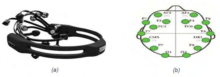
This unit depends on acquiring brain signals by using special devices such as Emotive EEG headset, Gamma cap (EEG cap), OpenBCI Ganglion, and Scalp Electrode. The diversity of signal extracting devices enabled researchers to use several methods to extract the brain signal that differs according to the used device. Angelakis D, Kasim MAA, Beyrouthy T [4, 7, 14] are using a commercial Emotive EEG headset with 14 sensors as shown in Figure 1a [14]. The Emotive EEG headset is a wireless device that captures EEG signals from the human brain and transfers it to a computer device. The sensors are putting together in a particular form that matches 10 -20 International System Positions AF3, F7, FC5, T7, P7, O1, O2, P8, T8, FC6, F4, F8, AF4, and 2 reference sensors as shown in Figure 1b [14].
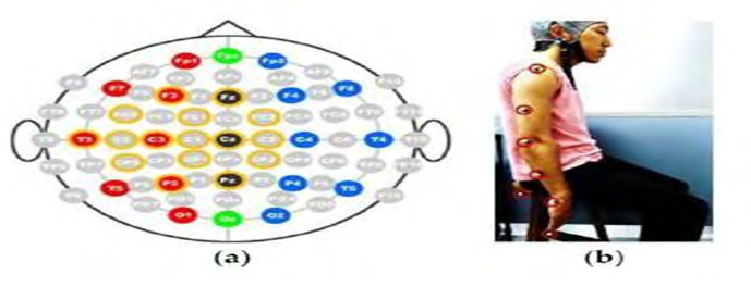
The Emotive EEG headset provides many pros that encourage the researchers to use it in many instants so its use is not limited to the laboratory, it’s a low-cost, non-invasive device with a wireless connection and accurate signal acquisition. On the other hand the main con of the Emotive EEG headset that the acquired signals still less accurate comparing with invasive BCI acquisition techniques. Bandara DSV [5] uses a Gamma Cap with 16 electrodes to record EEG signals and a Motion Capture System to enhance the signal by recording the motion of the upper limb. The used Gamma Cap contains 16 electrodes distributed by followed the 10 – 20 International System Positions at the Fz, F3, FC2, FC1, FC5, C2, Cz, C1, C3, C5, T3, Cp2, Cp1, Cp5, Pz, and P3 as shown in Figure 2a. The electrodes transfer the brain signals from the electrodes to the biosignal amplifier. Then, elbow motion and hand endpoint motion are estimated using a motion capture system as shown in Figure 2b.
The advantages of the Gamma cap are the accuracy of the signal and the number of electrons. It is available in different sizes for adults and pediatrics with a different number of electrodes from 16 up to 128 electrodes. But the disadvantages of the Gamma cap are: It is expensive and its appearance mirrors that of a robot.
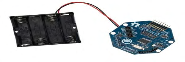
Korovesis [12] uses an OpenBCI Ganglion board as shown in Figure 3, it is an affordable bio-sensing device with 4 input channels, a driven ground (DRL), a positive voltage supply (Vdd), and a negative voltage supply (Vss), the data is sampled at 200Hz on each of the 4 channels [16]. For acquiring alpha brain waves, 4 Gold plated electrodes were connected to the input channels then placed on the scalp of the participated subject at the positions O1, O2, and A1, A2 for the reference electrodes.
The pros of the OpenBCI Ganglion board are: inexpensive, its use is not limited to the laboratory, easy to use, capable to capture EEG and ECG signals. But when comparing with invasive BCI acquisition techniques still that the acquired signals are less accurate.
Mohiddin M [15] uses Scalp Electrode for capturing the brain signals. The electrodes are connected to an instrumentation amplifier and bandpass filter to amplify and refine the signal. The advantages of using the Scalp Electrodes are inexpensive, used to capture EEG and EMG signals, and portable. The disadvantages of using Scalp Electrodes are less accurate in signaling, the acquired signals are difficult to analyze without the signal amplifier, and the use of wires for connection.
Signal Processing Unit (Processing Stage)
It is the second stage of BCI which arises after the brain signal is obtained. The acquired signal is then amplified, analyzed, and converted into signals that can control or influence a particular device. Therefore, other sub-processes may be performed in order to process the acquired signals such as preprocessing, feature extraction, and classification [11].
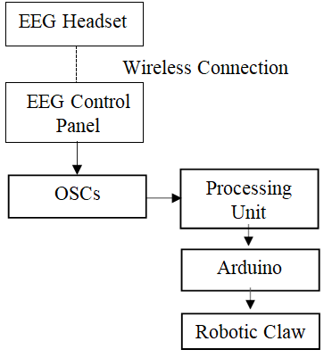
As maintained by Angelakis D [4], the Signal Processing Unit componence are: PC, Free Software (Emotive control panel), Open Sound Control (OSC) Software, and an Arduino Uno microcontroller. The PC received the signals from the EEG headset then the Emotive control panel software interpreted the EEG signals and sent them to OSC Software, the OSC Software encode the received data into a series of OSC messages then translate it to commands by using developed software using Java language, then the Arduino Uno microcontroller received the commands and move the servo motors as shown in Figure 4.
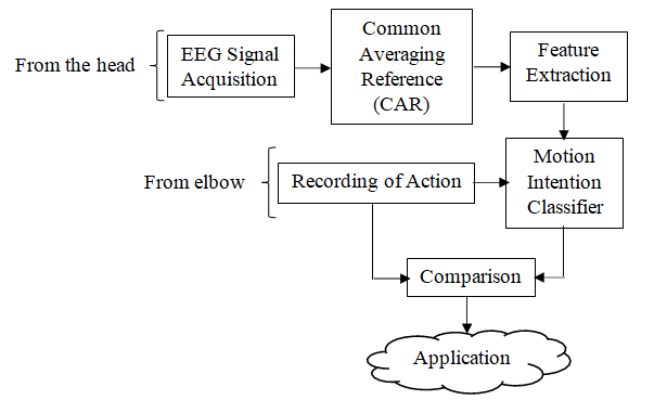
In the Signal Processing Unit for Bandara DSV [5], the brain stimulated for the wanted motion intention simultaneously with the elbow and hand endpoint motion data from the contributors, then the feature extracted by common averaging reference (CAR), next, the extracted feature is used to instruct the motion intention classifier. Finally, the output from the motion classifier is matched with the motion of the remaining limb, and the movement is created as shown in Figure 5.
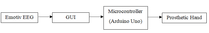
According to Kasim MAA [7], the Signal Processing Unit contains a PC, LabVIEW software, and an Arduino Uno microcontroller. The LabVIEW Software (GUI) received the face expression signals from the EEG headset (Smile and Looking right) and process serial data to the Arduino, the Arduino Uno microcontroller received the commands and move the Prosthetic Hand accordingly: If the user smiles the Prosthetic Hand will be open. If the user is looking right the Prosthetic Hand will be closed as shown in Figure 6.
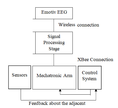
According to Beyrouthy T [14], the Signal Processing Unit contains a Raspberry Pi III microcomputer interfaced with an Arduino Mega microcontroller. The microcomputer received the digital signal from the EEG headset and compare it with a set of patterns, the microcomputer was programmed with multiple hand reflexes triggered by smart sensors network embedded in the arm, then the microcontroller handles the mechanical servo units installed in the arm as shown in Figure 7.
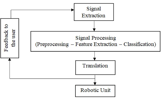
Korovesis [12] uses Signal Processing Unit that contains an OpenBCI Ganglion, Raspberry Pi III microcomputer, and Arduino Uno microcontroller. The BCI device was used in order to capture the alpha brainwaves, the microcomputer received the signals from the BCI device and compare them with the neural network built. Once a specified command according to the eyes’ blinking of a human operator is received by the Raspberry Pi, it is relayed to the microcontroller to achieve a specific movement as shown in Figure 8.
As stated by Mohiddin M [15], the Signal Processing Unit contains an Instrumentation Amplifier, a Band Pass Filter,
Comparison
and an Atmega328p microcontroller. The picked brain waves amplified by passing through instrumentation amplifier, amplified brain waves pass-through Band-Pass filter to filter out unnecessary frequency then send the desired signal to the microcontroller, the microcontroller performs the conversion of the signals from analog to digital form then send the digital signals to the LED, the LED becomes ON/ OFF according to the different states of brain concentration/ relaxation as shown in Figure 9.
Output Unit (Effector Device)
It is the last stage of the BCI system that shows the effect or the result. The output usually a movement or action either on a device or on a computer screen. Different effector devices have been used according to covered studies such as Robotic Claw [4], Prosthetic Hand [7], Transhumeral prosthesis [5], Prosthetic Arm [14], Robotic Unit [12], and LED [15].
| Input Unit (Signal Acquisition) | Signal Processing Unit | (Output Unit) Effector device | Used software | Strength points | Weakness points |
|---|---|---|---|---|---|
| Emotiv EEG Headset | The laptop received the signals from the headset receiver then the Emotive control panel software package taken the EEG signals and sent them to the OSC software package. The OSC Software package encodes the received knowledge into a series of OSC messages then translated them to instructions using a developed software package using Java language. The Arduino Uno microcontroller received the commands and move the servo motors. | Robotic Claw | The wireless communication protocol between the Emotiv EEG and the PC. Open Sound management protocol. Program to decode and convert OSC messages to command for the Arduino. | The use of free software for manipulating the EEG headset signals. | The execution of predefined movements. Required training session for the user. |
| Gamma cap to record EEG signals. Motion capture & System to record the motion of the upper limb | Brain activations for the desired motion intention together with the motion data from the participants. Then the data are preprocessed for feature extraction by averaging. | Transhumeral prosthesis | Artificial Neural Networks classifier. K-Nearest Neighbor classifier | The proposed hybrid technique has strengthened the implementation of the desired movement. | The execution of predefined movements. Required training session for the user. |
Next, extracted features are used to train the motion intention classifier. Lastly, the output from the motion intention classifier is compared with the motion state of the residual limb and the final decision is generated.
The LabVIEW Software (GUI) received the face expression signals from the EEG headset (Smile and Looking right) and process serial data to the Arduino. The Arduino Uno microcontroller received the commands and moved the Prosthetic Hand accordingly: If the user smiles, the Prosthetic Hand will be open. If the user is looking right the Prosthetic Hand will be closed.
Prosthetic Hand
Emotiv EEG Headset
The personal computer received the digital signal from the Emotiv EEG and compare it with a collection of patterns. The personal computer is programmed with multiple hand reflexes, triggered by a sensible sensors network embedded within the arm.
Emotiv EEG Headset
Prosthetic Arm
3. The microcontroller handles the mechanical servo units put in within the arm.
The BCI device was used, to capture the alpha brainwaves. The microcomputer received the signals from the BCI device and compare them with the neural network built. Once a specified command according to the eyes’ blinking of a human operator is received by the Raspberry Pi, it is relayed to the microcontroller to achieve a specific movement.
Scalp Electrode connected with OpenBCI Ganglion
The wireless communication protocol between the Emotiv EEG and also the laptop. GUI was produced by using the free LabVIEW software.
The execution of predefined movements. Required training session for the user.
1. The use of free software for manipulating the EEG headset signals The wireless communication protocol between the Emotiv EEG and also the embedded microcontroller within the prosthetic arm. Program to compare between the EEG reading and a collection of premeasured patterns associated with completely different The system was supported each autonomous (Smart sensors network) and semi- autonomous manage ment (Brain Signal). The utilization of Raspberry Pi III personal The execution of predefined movements. A needed coaching session for the user.
states of the mind (Raspberry Pi III). 3. Program to regulate the mechanical servo motors put in within the arm (Arduino Mega microcontroller) computer as interface. 4. The sensing element Network.
The execution of predefined movements.
The Control system guides the motion of a mobile robot via asynchronous and endogenous EEG- based BCI Required training session for the user.
Robotic Unit 1. Machine learning technique.
The use of the Wires for the connections.
| Scalp Electrode connected with Instrumentation Amplifier | The picked brain waves are amplified by passing through an instrumentation amplifier. Amplified brain waves pass through the Band-Pass filter to filter out unnecessary frequency then sends the desired signal to the microcontroller. The microcontroller performs the conversion of the signals from analog to digital form then sends the digital signals to the LED. The LED becomes ON/OFF according to the different states of brain concentration/relaxation. | LED | Discrete Fourier Transform (DFT) | Minimal Implementation of Brain- computer Interface | The use of the Wires for the connections. Required training session for the user. |
|---|
Table 2: Shows the outline of the comparison between the assorted strategies that are mentioned to use the BCI system [4,5,7,12,1
Challenges
The brain-computer interface (BCI) as the next technological achievement that blurs the line between science fiction and scientific reality faces many challenges. [3] listed that, most BCI research is done under heavily controlled environment, the technology must reach a stand-alone status to be in the reach of patients and health providers, the ‘BCI illiteracy’ that is a percentage of people that are unable to use BCI due to advanced stages of neuromuscular diseases or other unknown reasons, and the long training times. Depending on [4], directly accessing and using the raw EEG data and using pattern recognition techniques is one of the challenges. Korovesis [12] listed some challenges as the task completion time, mental workload of participants, and the detrimental effect of artifacts on EEG data that can be removed by using modern algorithms that combine source decomposition with blind source separation and adaptive filtering. According to Abdulkader SN [13], improving signal quality, more compact and stylish system designs, and improving the reliability of BCI by teaching and training the users to the BCI skills are some of the main challenges for the BCI.
Conclusion
This review concludes that different models can be used to implement brain-computer interface systems, differing in terms of cost, pros, and cons. However, we find that the problem of pre- training to use the systems is a major obstacle to the spread of this technology and making it popular in use by the general public. On the other hand, brain-computer interface systems that contain pattern recognition and machine learning algorithms are very expensive. Therefore, researchers and developers must balance the effectiveness and cost of BCI systems. The aim of our proposed is to record the EEG by means of electrodes. Form (table 1), it is clear that many hardware can be used for proposed, but the most quality and less price for homemade technology is raspberry minicomputer. The software part will include a classifier written in (python language). The output will be (LEDs) or servo motors.
References
-
Wolpaw J, Wolpaw EW (2012) Brain-computer interfaces: principles and practice. OUP USA.
-
Rao RP (2013) Brain-computer interfacing: an introduction. Cambridge University Press.
-
Ortiz Rosario A, Adeli H (2013) Brain-computer interface technologies: From signal to action. Rev Neurosci 24(5): 537-552.
-
Angelakis D, Zoumis S, Asvestas P (2017) Design and Implementation of a Brain Computer Interface System for Controlling a Robotic Claw. Journal of Physics: Conference Series 931: 012001.
-
Bandara DSV, Arata J, Kiguchi K (2018) Towards Control of a Transhumeral Prosthesis with EEG Signals. Bioengineering (Basel) 5(2): 26.
-
Coogan CG, He B (2018) Brain-computer interface control in a virtual reality environment and applications for the internet of things. IEEE Access 6: 10840-10849.
-
Kasim MAA, Low CY, Ayub MA, Zakaria NAC, Salleh MHM, et al. (2017) User-Friendly LabVIEW GUI for Prosthetic Hand Control Using Emotiv EEG Headset. Procedia Computer Science 105: 276-281.
-
Matlack CB, Chizeck HJ, Moritz CT (2016) Empirical movement models for brain computer interfaces. IEEE Transactions on Neural Systems and Rehabilitation Engineering 25(6): 694-703.
-
Murphy MD, Guggenmos DJ, Bundy DT, Nudo RJ (2016) Current challenges facing the translation of brain computer interfaces from preclinical trials to use in human patients. Frontiers in Cellular Neuroscience 9: 497.
-
Darmakusuma R, Prihatmanto AS, Indrayanto A, Mengko TL (2018) Hybrid Brain-Computer Interface: a Novel Method on the Integration of EEG and sEMG Signal for Active Prosthetic Control. Makara Journal of Technology 22(1): 28.
-
Ramadan RA (2015) Basics of Brain Computer Interface. 74: 31-50.
-
Korovesis N, Kandris D, Koulouras G, Alexandridis A (2019) Robot Motion Control via an EEG-Based Brain- Computer Interface by Using Neural Networks and Alpha Brainwaves. Electronics 8(12): 1387.
-
Abdulkader SN, Atia A, Mostafa MSM (2015) Brain computer interfacing: Applications and challenges. Egyptian Informatics Journal 16(2): 213-230.
-
Beyrouthy T, Kork SKA, Korbane JA, Abdulmonem A (2016) EEG mind controlled smart prosthetic arm. IEEE.
-
Mohiddin M, Premalatha M, Kedarnath B, Kumar KS, Prasad VK (2017) Implementation of Brain–Computer Interface Technology using Arduino. International Journal of Electrical Engineering & Technology 8(2): 25- 35.
-
https://shop.openbci.com/products/ganglion- board?variant=13461804483.
- Origin, Evolution, and Functional Impact of Short Insertion- Deletion Variants in Human Genomes: A Review
- Harnessing Molecular Glues for Next-Generation Vaccine, Cancer and Cardiovascular Disease Drug Development: A Comprehensive Review
- Lateral Cervical Epidermal Inclusion Cyst in a Paediatric Patient: A Rare Case Report
- Malarial Plasmodium Falciparum with Hepatitis B and C Virus Infections among Blood Donors in Ife Central Local Government Area, Ile Ife, Osun State, Nigeria
- Withanolides and Withaferin A- What’s next in Ashwagandha Research
- Designing of Dual Pulse Photoacoustic Tomography for Imaging of Drug-Response and Tumor Growth