Completion Design to Remove and/or Replace the Existing Completion in a Well and in Single Trip
Introduction
The purpose of drilling a well is to confirm or refuse the presence of hydrocarbons [1, 2, 3]. It is well known that at this stage, that the majority of wells to drill are dry. So, there is no need to spend much money on them. For the other wells, further research is conducted, and if the hydrocarbons reserve is found to be commercially viable, then some special equipment must be installed in the well to start production: This is known as completing the well [4, 5, 6]. Completion is the interface between the reservoir and the surface facilities [7, 8, 9, 10]. Without it, it is impossible to produce a well safely and efficiently. The completion string must be designed to reach the production objectives.
In some cases, certain wells are shut in after being produce during a certain moment of life due to the significant amount of sand and fines accumulating in the wellbore and surface facilities, thus negatively affecting production. To reactivate these wells, remedial sand control techniques will be necessary to restore and significantly increase the productivity [11, 12, 13, 14]. Remedial sand control is a costly operation. In fact, an oil price of $50 per barrel is needed to break even this type of projects. These costs include completion costs and workover. Remedial sand control costs are even higher due to longer operation times. In recent years, several studies have been carried out to determine which completion method is the most economical [15, 16, 17, 18]. Actually, the best completion method doesn’t exist. It all depends on the application. But to reduce the overall cost of remedial sand control, the simple idea is to conduct the operation effectively in single trip. The aim of this paper is therefore to design a completion that will enable to repair sand control of an existing well X in single trip and in an efficient manner. Is it technically feasible? To design effective completion, we need to perform the following tasks: Evaluate the completion design of the existing well X; select the most suitable completion method and corresponding equipment; choose the appropriate materials so that the equipment can be used during the entire life of the well; draw the completion schematic and write installation procedures. This paper is structured in three sections: The first section deals with the introduction, the second section presents the data, tools and the obtained results. The paper ends by general conclusion.
Data, Methods and Results
To preserve the data confidentiality, the well will be named “X’’ (for confidential reasons) and its location not given. In that field, several vertical wells which had initially produced an average of 160 BOPD, 55 BWPD and 1.28 MMcf/D gas had switched to 13 BOPD, 7 BWPD and 935 Mcf/D gas with 1,624 psi flowing tubing pressure and are shut in and not producing because of the significant amount of sand and fines produced to surface facilities and filling the tubing, thus negatively affecting production. The original gravel pack consisted of 82.5 mMD of 4-1/2-inch. 0.006-gauge screen set across the perforations at 2500mMD to 2595 mMD. A nipple was 2310 mMD above the top perforations in the 4-1/2- in. tubing. The average deviation through the completion interval was 40°. Through-tubing recompletion is expected. The reservoir pressure is 4200 psi, and the temperature is 115°C. The produced fluid is oil with API gravity of 32. It is a naphthenic type of fluid, and its aromatic fraction is very low. H2S content is low (4 ppm), and CO2 content is high (4.2 mole %). The true vertical depth of the well is 3000 mMD. The used data are summarized in Table 1.
| Reservoir data | Temperature =115°C |
|---|---|
| Pressure =4200 psi | |
| Fluid API gravity =32 | |
| Fluid type = Naphthenic | |
| H S content = 4ppm; CO content 2 2 =4.2 mole % | |
| PSD: 1680 µm | |
| Thickness = 246 ft | |
| Skin =2 | |
| Well data | TVD = 3000 Mmd |
| Inclination =40° @ 2000Mmd | |
| Production objectives | Production strategy =1 zones |
| Remedial objectives | Operation in a single trip |
| Clean out pressure = High (not above reservoir breakdown pressure ) |
Table 1: Data for well completion design.
The initial well schematic is illustrated in Figure 1.
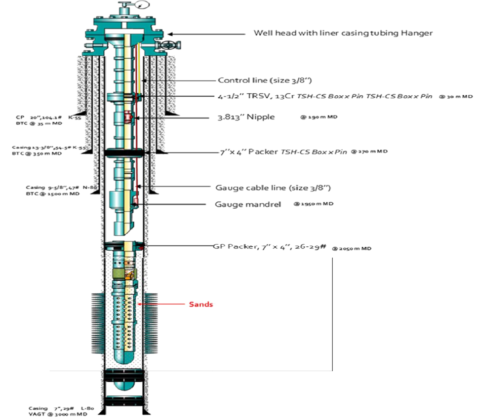
The initial well shown in Figure 1 is made of 4 casings (20” conductor pipe at 35mMD, 13-3/8” surface casing at 350 mMD, both grades are K-55 BTC, 9-5/8’’ intermediate casing at 1500mMD grade N-80 BTC and 7’’ production casing at 3000 mMD grade L-80). The upper completion is 4-1/2” with a tubing retrievable safety valve to control the well at 30 mMD, a gauge mandrel at 1950mMD measures temperature and pressure, a landing nipple above the production packer allow to set plugs and a hydro-trip sub below the production packer allow packer setting. The tubing size is 4-1/2” with a 18 nominal weight of 11.6 pounds per feet. Its grade is L80. The level of sand is into the production tubing. The Lip-Draw software and economic evaluation are used to attain the aims of this paper. This is made possible through material selection, choosing the working pressure and temperature, the screen size based on the particles size distribution, selecting the best completion method and describing the installation procedure.
Material and Equipment Selection
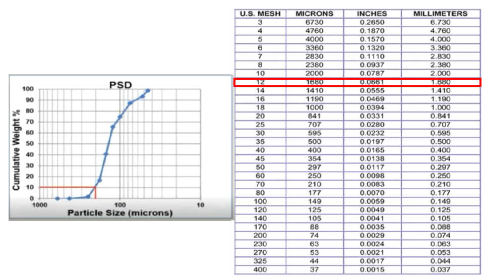
To choose the appropriate materials so that the equipment can be used during the entire life of the well it is necessary to analyze the well propose in terms of H2S and CO2 contents, which dealing element to use, find what will be the diameter and tubing nipple size that the screen will take according to the size of sand particles. The partial pressure of CO2 is 105 psi and the partial pressure of H2S is 0.021 psi. By using the first-pass selection graph, the recommended metallurgy is an alloy with 13 % of Chromium (13Cr). Moreover, the reservoir temperature is 115 °C, which is 239 °F. At this temperature, Sumitomo metals Industry [19] found that 13Cr have a lower corrosion rate than 9Cr. The reservoir temperature is 239 °F in the application range of nitrile, the H2S content is 4 ppm, which is less than 10 ppm, and the fluid is not aromatic. But the operating temperature is too close to the upper limit of nitrile temperatures. In this case, the best solution is to use hydrogenated nitrile or hydrogenated nitrile butadiene rubber. To cover the expected plan which is to restore and maintain the productivity as longer as possible, specific screen mesh size is choose based on the obtained particles size in the reservoir as shown in Figure 2.
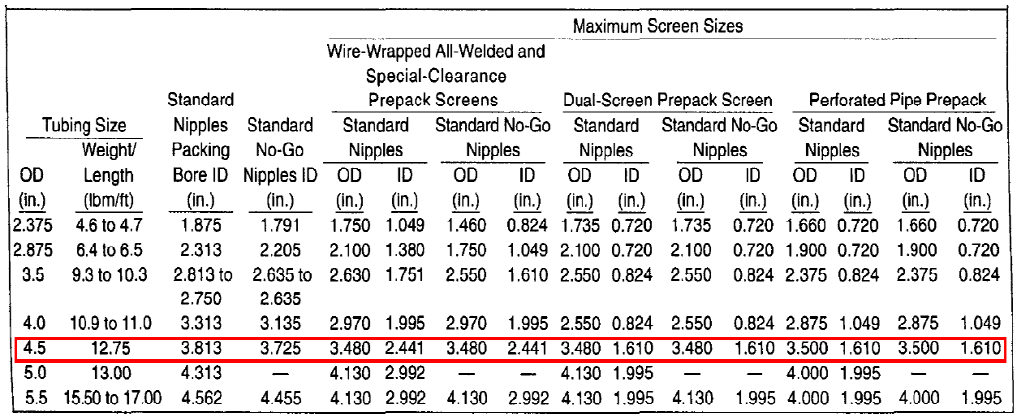
As the selection of the screen size depends directly on tubing and nipple restriction. Figure 3 shows the chosen appropriate screen size based on the existed tubing and nipple restriction.
The working pressure of the proposed equipment is 5000 psi and its temperature above 239 °F.
Well Schematic and Running Procedure
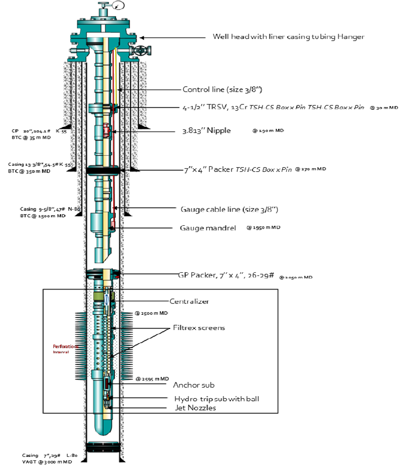
In the literature, the two most commonly used techniques for a remedial sand control are the mechanical method and the chemical method. In this paper, it is demonstrated that the most appropriate method is the innovation mechanical method which uses filtrex and involves single trip by eliminating workover operation. The older methods require multiple wirelines, workover and/or coiled tubing runs to place the screen at the desired depth and fulfil the operation. This increases the time and costs to perform the operation. And the operation constraint is clearly to perform the operation in a single trip so that less rig time is needed and high costs are saved. Figure 3 illustrates the proposed completion design.
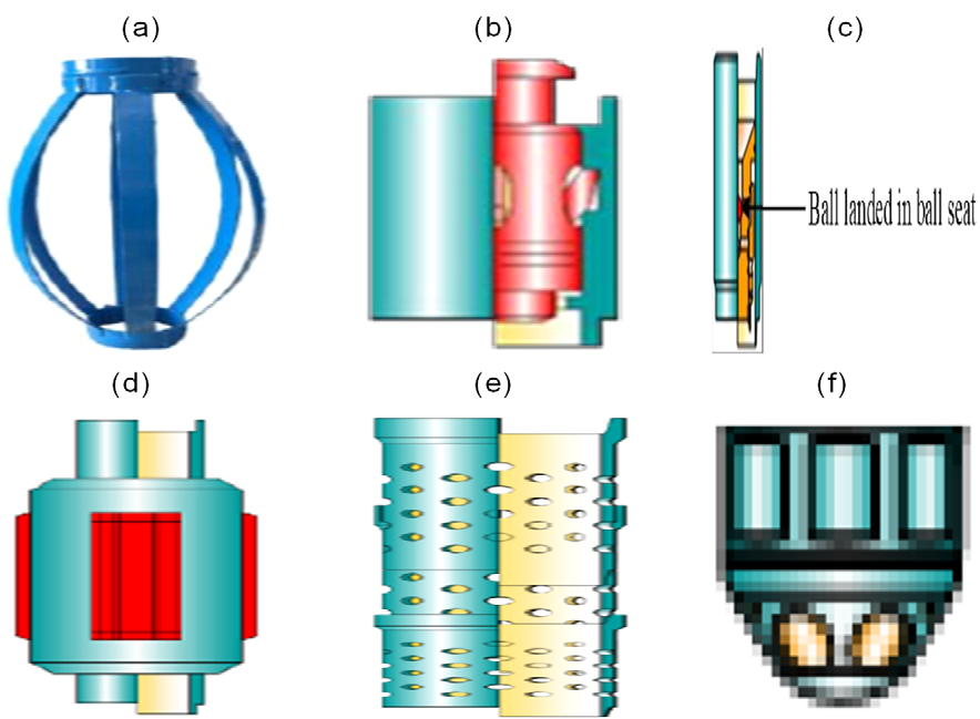
The used method in this paper is filtrex which consists of sleeve, plugging device, 9 sand baffles, anchor sub, centralizer and jet nozzles as shown in Figure 4.
When deployed on coiled tubing the installation of the system is performed over four stages and has the potential to significantly improve the financial feasibility of restoring production to failed wells as shown in Figure 5.
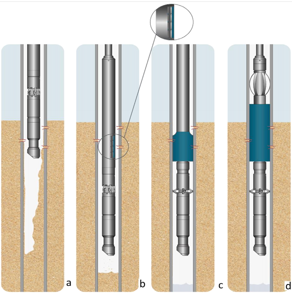
Initially in Figure 5a, the filtrex system screwed together is run in the well filled of sand particles. An injected fluid with a specific gravity lower than the reservoir fluid equivalent specific gravity so that its pressure is lower than the reservoir pressure. The filtrex system is run in hole to depth using a running tool with compression outer sleeve. Prior to expansion of the system, clean up fluid will be injected and the jetting nozzles will activate and commence sand clean out and any chemical treatment as shown in Figure 5b. Once the clean-out is complete a ball is dropped in the hydro-trip sub and pressure applied to activate the high expansion anchor deployed below the filtrex screen. In Figure 5c, the anchor sub is activated and locked into the existing 4-1/2’’ failed screen. Once set, the running tool and compression sleeve removal enables the polymer filter to expand and conform to the inner diameter of the failed screen; anchors are locked in tubing and centralizer is released. The filling of the annular gap prevents further ingress of reservoir solids into the wellbore while still allowing passage of liquids or gases. The running tool and compression sleeve is then retrieved from the well Figure 5d.
Economical Evaluation
The cost of the equipment to the rig cost is added to estimate the cost of each method. The results are shown in the Tables 2-4.
| Item | Cost/unit ($) | Unit | Cost ($) |
|---|---|---|---|
| Mechanical packer | 8,000 | 3 | 24,000 |
| Plugging device | 4,000 | 1 | 4,000 |
| Blank pipe | 5,000 | 1 | 5,000 |
| Screen | 3,500 | 9 | 31,500 |
| Sand control valve | 3,00 | 1 | 3,000 |
| Total cost ($) | 67,500 |
Table 2: Equipment cost for the “mechanical” method.
| Cost /unit ($) | Unit | Cost ($) | |
|---|---|---|---|
| Chemical products | 15,000 | 1 | 15,000 |
| Cut Packer | 25,000 | 1 | 25,000 |
| Total cost ($) | 40,000 |
Table 3: Equipment cost for “chemical” method.
| Cost/unit ($) | Unit | Cost ($) | |
|---|---|---|---|
| Sleeve | 1,100 | 1 | 1,100 |
| Plugging device | 4,000 | 1 | 4,000 |
| Jetting nozzle | 500 | 1 | 500 |
| Filtrex screen | 2,500 | 9 | 22,500 |
| Anchor sub | 1,000 | 1 | 1,000 |
| Centralizer | 500 | 1 | 500 |
| Total cost ($) | 29,600 |
Table 4: Equipment cost for the “Filtrex” method.
When comparing the cost of the required equipment for mechanical and chemical, it appears that chemical completion is most economical. But the chemical method requires coiled- tubing interventions for cleaning and pumping the fluids. It was estimated that the time to rig up and rig down is 48 hours. And the rig cost is estimated at 500,000 $ per day. So one hour will cost 20,833.33 $ approximately. The service charge is estimated at 250 $ per day; so one hours will cost 10.41 $. The operation costs for both projects are shown in the Tables 5-7.
| Cost/Time ($/hr) | Time (hr) | Cost ($) | |
|---|---|---|---|
| Workover rig | 20,833.33 | 48 | 999,999.84 |
| Workover Service | 10.41 | 48 | 499.68 |
| Total cost ($) | ####### |
Table 5: Operation cost for “mechanical” method.
| Cost/Time ($/hr) | Time (hr) | Cost ($) | |
|---|---|---|---|
| Coil tubing | 20,833.33 | 8 | 166,666.64 |
| Service | 10.41 | 8 | 83.28 |
| Total cost ($) | 166,749.92 |
Table 6: Operation cost for “chemical” method.
| Cost/Time ($/hr) | Time (hr) | Cost ($) | |
|---|---|---|---|
| Coil tubing | 20,833.33 | 8 | 166,666.64 |
| Service | 10.41 | 8 | 83.28 |
| Total cost ($) | 166,749.92 |
Table 7: Operation cost for “Filtrex” method.
Now for mechanical method, the costs are estimated at 67,500 $ for equipment and $ 1,000,499.52 $ for operation. The total cost is, therefore, 1,067,999.52 $. For chemical method, the costs are estimated at 40,000 $ for equipment and 166,749.92 $ for operation. So the total cost is 206,749.92 $. For filtrex method, the costs are estimated at 29,600 $ for equipment and 166,749.92 $ for operation. The total cost, in this case, is 196,349.92 $. In this case, filtrex completion is more economical. So this is the completion that will be designed, and its technical feasibility will be discussed here.
Conclusion
The goal of this paper was to choose the best suited and cost-effective completion method without the requirement to perform a workover in well X of the field Y. To address this challenge the filtrex one trip remedial sand control constitute of Centralizer, flitrex screen, anchor sub, plugging device and jet nozzle have been chosen and installed thru- tubing, through the tightest of restrictions and will expand into the casing internal diameter filling all annular gaps. To make filtrex sand control a successful operation, all aspects must be planned ahead. This implies selecting the most appropriate materials, completion method and equipment. In the field Y a completion design to be done in a single trip was required. The best materials were an alloy of steel with 13% of chromium for metallurgy and hydrogenated nitrile for sealing elements. Chromium adds resistance to steel in a corrosive environment, and at 239 °F, 13% of chromium gave better results than 9%. Both nitrile and hydrogenated nitrile could be used in the presence of the produced fluid, completion fluid, but the downhole temperature was very close to the upper limit of nitrile applications, hydrogenated nitrile was finally validated. This completion method with equipment helped to repair sand control in a single trip and later produce it without contingency. The costs were estimated at 29,600 $ for equipment and 166,749.92 $ for operation of filtrex method. The total cost wais 196,349.92 $. It is reliable and straight forward, but this can work only if minimum tubing size is 4-1/2’’. Remedial needs acid to treat the formation before lower the filtrex assembly, the completion team must work closely with production engineers to optimize pumping rates and pressures. Corrosion engineers must be part of the team and carry further work to validate the proposed metallurgy.
References
-
Economides MJ, Hill AD, Economides CE, Zhu D (1994) Petroleum production systems. 2nd (Edn.), Prentice-Hall.
-
John RF, Richard LC (2017) Introduction to petroleum engineering. Wiley, New Jersey.
-
Alain M (2014) Geology and Geodynamics of Hydrocarbons. Encyclopedia of Energy 5: 11-15.
-
Davorin M, Marin C, Moslavac B (2012) Sand control in well construction and operation. Springer.
-
Montrose R (2009) Completion design manual. Planete energies 16: 5-10.
-
Schlumberger (2014) Defining completion. SPE 3: 50.
-
Ali S, Norman D, Wagner D (2002) Combined stimulation and sand control Specialized fracturing treatments. Geology 4: 20-23.
-
Matanovic D, Cikes M, Moslavac B (2012) Sand control in well construction and operation, Springer, Environmental Science and Engineering.
-
Penberthy W (1992) Sand control. SPE 8: 15-20.
-
Crumpton H (2018) Well control for completions and interventions. 1st (Edn.), Oxford: Elsevier.
-
Fowler SH, Sedotal WP, Restarick HI (1994) Through- tubing sand control techniques reduce completion costs. SPE Drill & Compl 9(4): 236-243.
-
King G (1998) An introduction to the basics of well completions, stimulations and workovers. 2nd (Edn.), Tulsa.
-
Jabbari H, Benson SA (2013) Hydraulic fracturing design optimization - Bakken case study. San Francisco. American Rock Mechanics Association, pp: 1-6.
-
Hugues P (2011) Remedial Sand Control, In Mature Field: Results & Lessons learnt from Through-Tubing Sand Screens Operations in the GG, Netherlands: Society of Petroleum Engineers.
-
Renpu W (2011) Advanced well completion engineering. 3rd (Edn.), Burlington, Elsevier.
-
Mathur P, Kumar N (2016) Contrast between plug-and- perf method and ball and sleeve method for horizontal well stimulation.
-
Eilidh M (2020) Technology advances in remedial thru- tubing sand control. 1st (Edn.), Tendeka, UK: Elsevier.
-
Dugstad A (2006) Fundamental aspects of CO2 metal loss corrosion - Part 1: Mechanism. Houston, International corrosion conference.
-
Sumitomo Metals Industries (2008) OCTG materials and corrosion in oil and gas production, Tokyo.
- Lessons to Learn: Trees are More than the Lungs of the World
- Community Forestry Enterprises as a Model for Sustainable Forest Development: The Case Of The "Baja Tarahumara" in Chihuahua, Mexico
- Ecological and Socio-Economic Impacts of Chromolaena odorata and Mesosphaerum suaveolens, Two Invasive Alien Species in Central and Southern Benin, West Africa
- Epigenetic Sustainability: Modeling the Human Factor as a Natural Resource through Science 4.0 and the NR3C1 Biological Pilot
- Growth-at-Risk: A Framework for Assessing Economic Vulnerability
- The Rural Territory as a Socioecological System for the Management of Public Policy for Sustainable Rural Development