Optimization Design of Heliostat Field Based on Biomathematical Models
The optimal design of heliostat field in solar power generation device is studied Heliostat field generates high temperature by focusing the sunlight reflected from the mirror surface, thus pushing the turbine to generate electricity. In order to improve the efficiency of power generation, this paper optimizes the parameters of heliostat field, establishes a single-objective optimization model, and uses mixed strategy whale optimization algorithm to solve it. Through geometric optical analysis and ray tracing model, the optical efficiency of heliostat field and the annual average output thermal power per mirror area are calculated. Finally, through the discussion and analysis of the model, the optimization design method is evaluated
Bin Zhao1*, Jiahao Mou1 and Xia Jiang2
Introduction
All human economic activities, production and life are closely related to energy. For a country, the increase of total energy consumption can promote the growth of gross national product [1]. As the largest developing country in the world, China has large reserves of non-renewable conventional energy resources such as coal, oil and natural gas, but China is a big energy producer and a big energy consumer. Accelerating the utilization of non-renewable conventional energy resources will inevitably lead to the intensification and deterioration of the contradiction between energy demand and energy supply, and at the same time, it will also pollute our environment, lead to excessive greenhouse gas emissions and global warming. Therefore, advocating the development of low-carbon renewable new energy is one of the key development directions in China. Under this background, solar energy is the most abundant and inexhaustible renewable energy on the earth and solar power generation technology has become the most suitable technology for renewable and clean utilization of electric energy.
The heliostat is a mirror that can rotate around the horizontal and vertical axes to adjust the reflection of sunlight. When the heliostat is working, the control system controls the normal direction of the heliostat in real time according to the position of the sun, so that the light emitted from the central point of the sun is reflected by the center of the heliostat and points to the center of the collector, and the height of the collector center from the ground is called the height of the absorption tower.
The sunlight reflected by the heliostat will be focused on the heat absorber located at the top of the heat absorber, heating the heat transfer medium circulating in the heat absorber, and storing the solar energy in the form of heat energy, and then realizing the conversion from heat energy to electric energy through heat exchange, and in this process, part of the sunlight will be lost through atmospheric transmission and mirror reflection, which will affect the overall optical efficiency of the heliostat.
Cosine loss is the loss of received energy caused by the fact that the incident direction of sunlight is not parallel to the normal direction of the mirror lighting port. Cosine efficiency represents the actual lighting area of the mirror, which is equal to the ratio of the actual lighting area of the heliostat to the mirror area. The smaller the included angle, the higher the cosine efficiency, and vice versa.
Shadow occlusion loss also has a great influence on the light efficiency of heliostats. Shadow loss refers to the loss caused by the incident light of a heliostat being blocked by one or more heliostats around it. Occlusion loss refers to the loss that the reflected light of a heliostat is blocked by one or more heliostats around it. In fact, the shadow and occlusion efficiency is the ratio of the mirror area without shadow and occlusion in the mirror field to the total mirror area in the mirror field [2].
Sunlight is not a parallel ray, but a cone-shaped ray with a certain cone angle, so the reflected ray of the sun’s incident ray passing through any point of the heliostat is also a cone- shaped ray [3]. The sunlight reflected by the heliostat will form a light spot. when it falls on the receiving surface of the heat absorber.
Due to the characteristics of sunlight and the precision or shaking of the heliostat, the light spot may shift or overflow, resulting in some light shining outside the heat absorber, and this overflow light spot will form a truncation loss.
We use whale optimization algorithm based on a hybrid strategy to optimize the arrangement of the heliostat field to achieve the greatest possible heating efficiency.
Establishment of Optical Efficiency Model
Establishment of Cosine Efficiency Model
After pre-processing the data, the due east direction is the X-axis positive direction and the due north direction is the Y-axis positive direction, and all the heliostats are marked in the plane coordinate system with Excel, we can get the general distribution map of all customized mirrors.
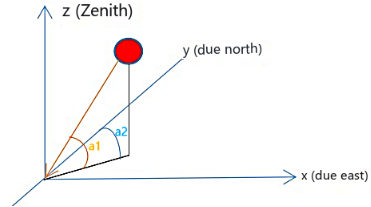
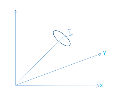
A coordinate system is established with the center of the circular area as the origin, the due east direction as the X-axis positive direction, the due north direction as the Y-axis positive direction, and the upward direction perpendicular to the ground as the Z-axis positive direction, which is called the mirror field coordinate system. The solar altitude angle
1 ( ) a s α refers to the angle between the incident light of the sun and the ground plane, and the sun azimuth 2 ( ) a s γ refers to the angle between the projection of the sun’s incident light on the ground plane and the true north direction, as shown in Figure 1.
According to the information in the appendix, the solar altitude angle and the azimuth of the sun. The calculation formula of is $$ \alpha s = \pi / 2 - \arccos \left(\cos \delta \cos \phi \cos \omega + \cos \delta \cos \phi\right) \tag {1} $$ $$ \gamma \mathrm {s} = \arccos \left[ \left(\sin \delta \cos \phi - \cos \delta \cos \omega \sin \phi\right) / \cos \alpha s \right] - \pi $$ (2) There must be an angle between the incident rays of the sun and the mirror normal of the heliostat. The cosine value Cosθ defining this angle is cosine efficiency and the angle θ is cosine angle. Suppose that the central coordinate of the heliostat mirror is (x, y, z), the coordinate of the target point on the heat absorber is (0, 0, h), and h is the height of the center point of the heat absorber from the ground, where s is the unit vector of the incident light of the sun, r is the unit vector of the reflected light of the mirror, and n is the unit vector of the normal of the mirror. In order to calculate the cosine efficiency, the heliostat concentrating schematic diagram [2] as shown in Figure 2 is established.
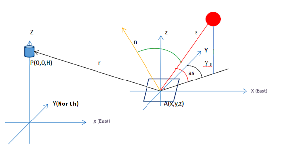
Point P is the coordinate of the collector, H is the height of the collector relative to the mirror field plane, A_(x, y, z) is the coordinate of the heliostat center (_z is the height of the mirror center relative to the mirror field plane), S is the direction vector of the sun’s incident light in the opposite direction (the direction is from the mirror reflection point to the sun), R is the direction vector of the sun’s reflected light, and N is the unit normal vector of the heliostat center is the angle between n and r.
According to the reflection law of mirror light, the incident angle of heliostat mirror is equal to the reflection angle, and the calculation formula of cosine efficiency is obtained by combining geometric vector method cos cos
|[1 cos(2 )]/ 2 |
$$ \eta_ {\cos} = \cos \theta = | [ 1 + \cos (2 \theta) ] / 2 | = \sqrt {(1 - s \times r) / 2} \tag {3} $$ $$ s = \left(- \cos (\alpha s) \sin (\gamma s), \cos (\alpha s) \cos (\gamma s), - \sin (\alpha s)\right) \tag {4} $$ $$ r = \left(- x, - y, H - z\right) / \sqrt {\left(x ^ {2} + y ^ {2} + \left(H - z\right) ^ {2}\right)} \tag {5} $$ But according to the simplification, you can get $$ = \vec {n} \times \vec {s} \tag {6} $$
Substituting the coordinates of each heliostat, the solar
altitude angle and the solar azimuth into the equation, we
can get the cosine efficiency in different months and different
time points in Excel, and then get the monthly average, and
then get the annual average of cosine efficiency.
cos n s η
Establishment of Shadow Efficiency Model
In the mirror field coordinate system established in 5.11, the coordinates of the collector are expressed as O (0, 0, H), where h is the height of the collector center relative to the mirror field plane. Assuming that the mirror center of the heliostat is located on the central axis of the pedestal, the mirror center coordinate of the heliostat A can be expressed as A (x, y, z) is the coordinate of the heliostat in the mirror field plane, and z represents the height of the mirror center relative to the mirror field plane. For any heliostat, the light from the sun must point to the center of the collector after specular reflection. The unit normal vector of the light from the mirror center of the heliostat pointing to the collector is R, and the unit vector of the incident light from the sun is S’.
$$ S ^ {\prime} = \left(x _ {i}, y _ {i}, z _ {i}\right) \tag {7} $$
The calculation formula is
cos( ) sin( ) x s s
α γ = = − =
i cos( ) cos( ) sin( )
y s s z s α γ α (8)
i i According to the law of light reflection, the normal vector of mirror surface is coplanar with the normal vectors of incident light and reflection light and bisects the included angle between incident light and reflected light. Therefore, the mirror normal vector of heliostat can be deduced from the normal vector of incident light and the normal vector of reflected light:
$$ n = \frac {r - S ^ {\prime}}{| r - S ^ {\prime} |} $$
(9) Then the pitch angle of heliostat can be calculated and azimuths ( ) ( )
sin tan cos 2cos sin cos s m z z x y m s s m x s y s
$$ \left\{ \begin{array}{l} \tan (\theta z) = \frac {\sin (\alpha s) m + z}{\sqrt {x ^ {2} + y ^ {2} + m ^ {2} \cos^ {2} (\alpha s) - 2 \cos (\alpha s) m \left[ x \sin (\gamma s) - y \cos (\alpha s) \right]}} \\ \sin (\theta s) = \frac {x - \cos (\alpha s) \sin (\gamma s) m}{\sqrt {x ^ {2} + y ^ {2} + m ^ {2} \cos^ {2} (\alpha s) - 2 \cos (\alpha s) m \left[ x \sin (\gamma s) - y \cos (\alpha s) \right]}} \end{array} \right. $$ α θ α α γ α ( ) ( ) ( ) ( )
2 2 2 2 ( ) ( ) ( )
cos sin sin cos 2cos sin cos x s s m s x y m s s m x s y s α γ θ α α γ α ( ) ( ) ( ) ( )
2 2 2 2 (10) among $$ m = \sqrt {\left(x ^ {2} + y ^ {2} + z ^ {2}\right)} \tag {11} $$ In the whole heliostat field, the shadow shading loss is roughly three parts
- Shadow loss refers to the loss that the incident light of a heliostat is blocked by one or more heliostats around it.
- Occlusion loss refers to the loss caused by the reflected light of a heliostat being blocked by one or more heliostats around it.
- The shadow loss caused by the tower to the mirror field is ignored.
In fact, the shadow and occlusion efficiency is the ratio of the mirror area without shadow and occlusion to the total mirror area of the mirror field, so we specifically study the shadow and occlusion that only occur in a certain range around the target heliostat, so as to find out the shadow efficiency of the whole mirror field.
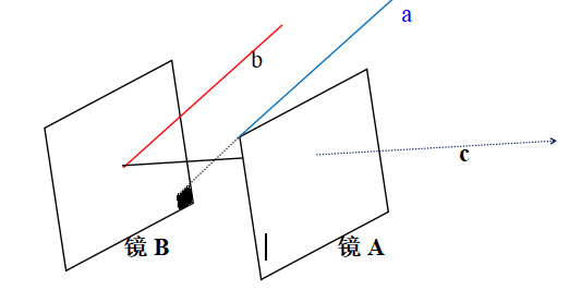
Select one heliostat in turn from the mirror field as the target heliostat A to be determined, and then select one heliostat other than the selected target heliostat A from the mirror field as the problem heliostat B that may interfere with the target heliostat A, as shown in Figure 3.
In the figure, A and B represent the incident rays of the sun, and C represents the rays reflected by the heliostat. As can be seen from the ray path in the figure, the incident rays A are blocked by the A mirror in the process of incident on the B mirror, thus causing a shadow on the A mirror B mirror, which is the shadow loss, while the reflected rays C reflected by the B mirror are blocked by the A mirror in the process of reaching the heat absorber, resulting in the light blocking phenomenon of the A mirror to the B mirror.
The process of calculating the shadow shading loss is actually to calculate whether any point of the A mirror will fall into the area of the B mirror along the opposite direction of the incident light or the reflected light, and to find out its mirror coordinate value in the B mirror.
Then the distance between heliostat A and heliostat B in the mirror field plane can be calculated, and it can be judged whether the problem B mirror is located in the range where mirror A may be shaded and blocked. If it is not within the target range, re-select the problem heliostat; otherwise, the next step is judged.
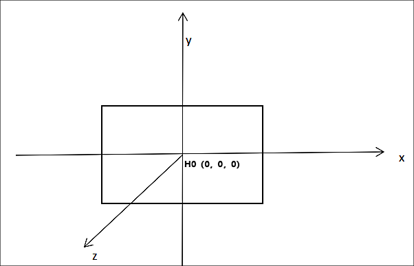
Establish the mirror coordinate system Figure 4. In the A-mirror coordinate system, a certain point in the A-mirror H1 = (x1, y1), and find the coordinate H2 = (x2, y2) where the passing light falls into the B-mirror coordinate system.
Suppose that the identity matrix of the transformation relation from the surface coordinate system A to the ground coordinate system B is [3]:
$$ ' = \left( \begin{array}{c c c} l _ {x} & l _ {y} & l _ {z} \\ m _ {x} & m _ {y} & m _ {z} \\ n _ {x} & n _ {y} & n _ {z} \end{array} \right) $$ l l l x y z (12) T m m m x y z n n n x y z Due to the pitch angle of the heliostat Z è and azimuth S è can be calculated, and we can convert into sin sin cos cos cos cos sin sin cos sin 0 cos sin z s z s z T z s z s z s s θ θ θ θ θ θ θ θ θ θ θ θ $$ Y = \left( \begin{array}{c c c} - \sin \theta z & - \sin \theta s \times \cos \theta z & \cos \theta s \times \cos \theta z \\ \cos \theta z & - \sin \theta s \times \sin \theta z & \cos \theta s \times \sin \theta z \\ 0 & \cos \theta s & \sin \theta s \end{array} \right) $$ (13) Suppose again that the vector of a ray (including incident ray and reflected ray) in the ground coordinate system is:
o V = (a, b, c), and its vector in mirror coordinate system is expressed as h V . Then $$ V _ {0} = T V _ {h} \quad (1 4) $$ In order to calculate the value of H2 = (x2, y2), firstly, a certain point of the A-mirror is converted to the coordinates in the ground coordinate system and expressed as.
$$ H _ {1} ^ {\prime} = T H _ {1} + O _ {A} = \left(x 1 ^ {\prime}, y 1 ^ {\prime}, y 2 ^ {\prime}\right) \tag {15} $$ where OA is the coordinate value of the origin of the A-mirror coordinate system in the ground coordinate system, which is expressed as (xA, yA, zA).
1. Then, in the ground coordinate system is transformed into the B-mirror coordinate system, which is expressed as.
$$ H _ {1} ^ {\prime \prime} = T ^ {T} \left(H _ {1} ^ {\prime} - O _ {B}\right) = \left(x _ {1} ^ {\prime \prime}, y _ {1} ^ {\prime \prime}, z _ {1} ^ {\prime \prime}\right) \tag {16} $$ where OB is the coordinate value of the origin of the B-mirror coordinate system in the ground coordinate system, which is expressed as (xB, yB, zB).
2. Convert the light (incident or reflected) in the ground coordinate system to the B mirror coordinate system.
$$ V _ {H} = T ^ {T} V _ {0} = (a, b, c,) \tag {17} $$
3. In the coordinate system of B-mirror, according to the principle of two points and one line, calculate the intersection point between light and B-mirror, and judge whether H2 is in the mirror.
Given the point “= (x1”, y1”, z1”) and the ray vector = (a, b, c) in the B-mirror coordinate system, find H2(x2, y2, 0).
Equation:
$$ \frac {x 2 - x 1 ^ {\prime \prime}}{a} = \frac {y 2 - y 1 ^ {\prime \prime}}{b} = \frac {- z 1 ^ {\prime \prime}}{c} \tag {18} $$ Solve and get:
1" 1" 2 cx ax x c cy bz y c
$$ \left\{ \begin{array}{l} x 2 = \frac {c x 1 ^ {\prime \prime} - a}{c} \\ y 2 = \frac {c y 1 ^ {\prime \prime} - b}{c} \end{array} \right. $$ (19)
1" 1" 2 Therefore, it is judged whether H2 falls within the scope of the mirror surface, and it is verified whether the B mirror is within the scope where the A mirror may be shaded and blocked. If it is not within the target range, re-select the target heliostat.
Otherwise, the next step is judged: the mirror normal vectors of the mirrors of heliostats A and B at the current simulation time point and the plane equations of heliostats in the mirror field coordinate system are calculated respectively; The vertex coordinates of heliostats A and B at the moment of calculation are calculated respectively, and the problem heliostats are divided into m and n mirrors according to the equal ratio of length and width.
Then calculate the position of the sun at the current time and the geometric parameters of the heliostat, and calculate the coordinate data of each mesh point. Starting from the first point in the mesh point, make a straight line through it (taking the direction vector of the incident light at the calculated moment as the direction vector), and find the intersection coordinates of the straight line and the plane where the target heliostat is located.
In the plane where the target heliostat is located, it is judged whether the intersection points are located in the rectangular area surrounded by the boundary of the target heliostat. Finally, the number of intersection points located in the target area is counted, and the ratio of the intersection points to the total intersection points is the shadow loss.
From this, we can get the shadow efficiency of heliostat field when the number of days and time change.
Establishment of Truncation Efficiency Model
The truncation efficiency is defined as the percentage of the energy intercepted by the heat absorber to the concentrated energy of the mirror field. Among them, the so-called “energy gathered by the mirror field” should be the solar energy that can be reflected by the whole mirror field, which needs to remove the solar energy that has been lost by shadow, light blocking and attenuation [3].
The incident light from the sun is a cone-shaped light with a half-angle width of 4.65_mrad_. According to the reflection principle, the light reflected on the heat absorber is also in a divergent cone shape.
In the divergence angle of the sun, a number of rays are evenly traced as incident rays, and the way of uniform tracing is to widen the square at half angle.
In the circumferential direction, the step size is also divided at a uniform angle, as shown in Figure 5.
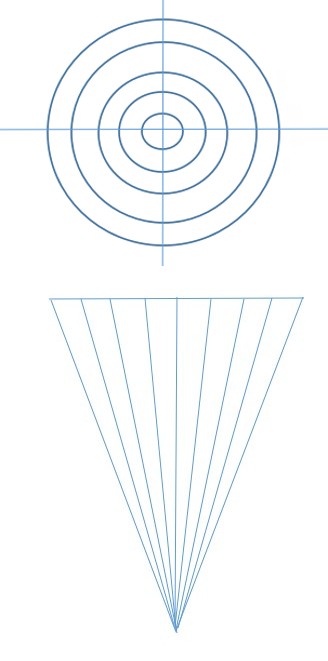
To find the expression of a ray in the cone, firstly, a cone coordinate system OS-XSYSZS is established. As shown in the figure, in a cone beam, Z_S_ is along the direction of the main ray and faces the center of the sun disk. X_S_ axis is always parallel to the ground and YS axis is perpendicular to X_S_ and Z_S_ axes.
Assuming that the included angle between any ray in the cone of light and the main ray from the sun center is σ, and the included angle with X_S_ is τ, the expression of any ray is:
$$ S _ {s} = \left(\sin \sigma \cos \tau , \sin \sigma \cos \tau , \cos \sigma\right) \tag {20} $$ A cone of light is composed of countless rays. Calculating the truncation efficiency or calculating the energy retention density on the heat absorber is to cumulatively calculate the landing coordinates of many rays when they reach the heat absorber after being reflected by the heliostat.
A cone of light is composed of countless rays, so calculating the truncation efficiency or the energy retention density on the heat absorber is to calculate the coordinates of the falling points of many rays after being reflected by the heliostat.
Taking a ray in a light cone as an example, 1) find the coordinate representation of point H1 in the mirror coordinate system in the ground coordinate system: a point H 1 of mirror A is converted into the coordinate in the ground coordinate system and expressed as:
' ' ' ' x H T H O y z
= × + =
1 (21)
1 1 1 A
1 Find the vector representation of any ray in the light cone in the ground coordinate system: suppose that the vector representation of this ray in the light cone coordinate system is V_s_ = (a, b, c).
The matrix conversion relation from light cone coordinate system to ground coordinate system is as follows:
sin sin cos cos cos cos sin sin cos sin 0 cos sin T γ α γ α γ γ α γ α γ α α $$ \gamma^ {\prime} = \left( \begin{array}{c c c} \sin \gamma & - \sin \alpha \cos \gamma & \cos \alpha \cos \gamma \\ - \cos \gamma & - \sin \alpha \sin \gamma & \cos \alpha \sin \gamma \\ 0 & \cos \alpha & \sin \alpha \end{array} \right) $$ (22) Then, the V_s_= (a, b, c) vector in the light cone coordinate system is transformed into the ground coordinate system.
In the department, get
$$ V _ {S} = T \times V _ {S} = \left(a _ {1}, b _ {1}, c _ {1}\right) \tag {23} $$ When calculating the vector of the reflected light in the ground coordinate system, the reflected light must be calculated according to the incident light and the actual normal of the mirror, because the light vectors in the light cone are different and the actual normal of the mirror is not constant.
Suppose the normal unit vector of the heliostat V_N_ = (U_0_, V_0_, W_0_).
The reflected ray vector of the ray after being reflected by the heliostat is found to be V_R_. The ray vector V_SL_ and the mirror normal vector V_N_ are both unit vectors, two vectors. The included angle is assumed to be θ, and the other chord values.
$$ V _ {n} = 2 \cos \theta V _ {N} - V _ {s l} = (m, n, l) \tag {24} $$
$$ \mathrm {s} \theta = \frac {V _ {s l} \times V _ {N}}{\left| V _ {s l} \right| \times \left| V _ {N} \right|} = V _ {s l} \times V _ {N} $$ cos | | | | sl N sl N sl N (25) Equation expression of reflected light $$ \frac {x - x _ {1}}{m} = \frac {y - y _ {1}}{n} = \frac {z}{l} \tag {26} $$ According to the equation of heating surface of heat absorber, the coordinates of light intersection point are solved. The equation expression of the reflected light has been obtained, and the intersection point of the reflected light on the heat absorber can be obtained by combining the equation of the receiving surface of the heat absorber, so the equation expression of the cylindrical heat absorber is $$ \left\{ \begin{array}{l} x ^ {2} + y ^ {2} = R ^ {2} \\ z \in \left[ - \frac {h}{2}, \frac {h}{2} \right] \end{array} \right. $$
2 2 2 x y R
+ , 2 2 h h z
(27) Where h represents the height of the heat absorber.
If the average annual occlusion efficiency is required, then we need to calculate the five moments separately, and calculate the average annual truncation efficiency and then accumulate the average annual truncation efficiency.
Solution and Analysis of the Model
The optical efficiency of heliostats is $$ \eta = \eta_ {s b} \eta_ {\cos} \eta_ {a t} \eta_ {t r u n c} \eta_ {r e f} \tag {28} $$ Atmospheric transmittance is $$ \eta_ {a t} = 0. 9 9 3 2 1 - 0. 0 0 0 1 1 7 6 d _ {H} R + 1. 9 7 \times 1 0 ^ {- 8} \times d _ {H R} ^ {2} \left(d _ {H R} ^ {2} \leq 1 0 0 0\right) $$ (29) Where d_HR_ represents the distance (unit: m) from the mirror center to the center of the collector.
The atmospheric transmittance of each heliostat is calculated by matlab, and the daily average optical efficiency is calculated by substituting the atmospheric transmittance when calculating the average optical efficiency.
Specular reflectivity η refs take a constant of 0.92.
Normal direct radiation irradiance DNI (unit: kW/m2) refers to the solar radiation energy received in unit area and unit time on the plane perpendicular to the solar rays on the earth, which can be approximately calculated according to the following formula.
$$ = G _ {0} \left[ a + b \exp \left(- \frac {f}{\sin \alpha_ {S}}\right) \right] $$ f DNI G a b α
0 exp sin S (30) $$ \int a = 0. 4 2 3 7 - 0. 0 0 8 2 1 (6 - 1 $$
2 ( )
0.4237 0.00821 6 a H
( )
2
0.5055 0.00595 6.5 b H $$ = 0. 5 0 5 5 + 0. 0 0 5 9 5 \left(6. 5 - 1\right) $$ (31) ( )
2
0.2711 0.01858 2.5 c H $$ = 0. 2 7 1 1 + 0. 0 1 8 5 8 \left(2. 5 - 1\right) $$ Where G_0_ is the solar constant and its value is 1.366_kw/m_2, and h is the altitude. The output thermal power E_field_ of heliostat field is N $$ E _ {f i e l d} = D N I \times \sum_ {i} ^ {N} A _ {i} \eta_ {i} \tag {32} $$ Where DNI is the normal direct radiation irradiance; N is the total number of heliostats (unit: surface); A_i_ daylighting for the first heliostat. Area (m2); Is the optical efficiency of the first mirror. According to Excel and Matlab, we can get the following data.
| Average Optical Efficiency | Average Cosine Efficiency | Average Shadow Shielding Efficiency | Average Truncation Efficiency | Average mirror output per unit area Thermal power (kW/m 2) | |
|---|---|---|---|---|---|
| January 21st. | 0.45 | 0.76 | 0.92 | 0.75 | 0.46 |
| February 21st. | 0.47 | 0.78 | 0.92 | 0.75 | 0.48 |
| Mar-21 | 0.47 | 0.79 | 0.92 | 0.75 | 0.5 |
| April 21st | 0.48 | 0.79 | 0.92 | 0.75 | 0.5 |
| May 21st. | 0.47 | 0.79 | 0.92 | 0.75 | 0.5 |
| June 21st. | 0.47 | 0.78 | 0.92 | 0.75 | 0.48 |
| July 21st. | 0.45 | 0.76 | 0.92 | 0.75 | 0.45 |
| August 21st. | 0.44 | 0.74 | 0.91 | 0.75 | 0.41 |
| September 21st. | 0.42 | 0.72 | 0.89 | 0.76 | 0.36 |
| October 21st. | 0.41 | 0.71 | 0.88 | 0.76 | 0.34 |
| November 21st. | 0.42 | 0.72 | 0.89 | 0.75 | 0.37 |
| December 21st. | 0.44 | 0.74 | 0.92 | 0.75 | 0.42 |
| Annual average optical efficiency | Annual average cosine efficiency | Annual average shadow shielding efficiency | Annual average truncation efficiency | Annual average output thermal power (MW) | Average annual output thermal power of mirror per unit area (kW/m 2) |
| 0.45 | 0.76 | 0.91 | 0.75 | 27.57 | 0.44 |
Table 1: Average optical efficiency and output power on 21st day of each month.
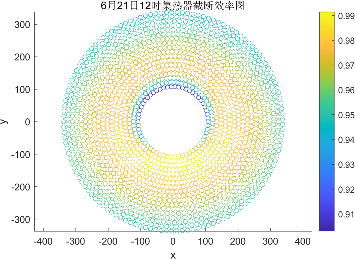
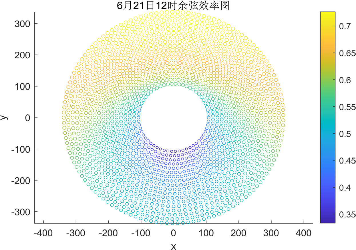
By analysing the data, it can be found that the monthly average optical efficiency is the largest on the summer solstice (June 21st), and the truncation efficiency, cosine efficiency and total optical efficiency of each heliostat are marked with different colours, as shown in Figures 7 & 8. It can be observed that the cosine efficiency and total optical efficiency of heliostats in the north of the whole field are higher.
Optimal Arrangement of Heliostat Field
Optimal Model of Heliostat Field
Max {expression of annual average output power per unit mirror area}
St. Constraint 1: Restrict the related quantity of output power. In this study, we use heuristic algorithm as the solution algorithm to find the optimal arrangement of heliostat field. We provide three alternative optimization algorithms. By adjusting the radial spacing of heliostats in different areas, the heliostat field is arranged to ensure that no mechanical collision will occur between adjacent heliostats, that is, the constraint condition of $\Delta r$ is
$$\Delta r \geq \cos 30^\circ d = 0.866d$$
Independent Variable
Take the position $(0,0)$ of the absorption tower as the origin of the coordinate axis, and the coordinate system is the same as the first question.
- Heliostat size: length $a$; width $b$
- Installation height: $h_1$
- Height of the center of the collector: $h_2$
- Number: $n$
- Location: $(x_n, y_n)$
Optimization Objective
$$\max \left( E_{field\_ave} = \frac{E_{field}}{n \times a \times b} \right)$$
Objective Function
$$E_{field\_ave} = f(a, b, h_1, h_2, n)$$
Constraint Condition
$$\begin{cases} 5 + b \leq \sqrt{\left(x_n - x_{n-1}\right)^2 + \left(y_n - y_{n-1}\right)^2} \\ 5 + b \leq \sqrt{\left(x_n - x_{n-1}\right)^2} \\ 5 + b \leq \sqrt{\left(y_n - y_{n-1}\right)^2} \\ 5 \leq a < b \leq 8 \\ 2 \leq h_1 \leq 6 \\ 4 \leq h_2 \leq 76 \\ P \geq 60MW \\ 100 \leq \sqrt{x_n^2 + y_n^2} \leq 350 \end{cases}$$
EP layout
Characteristic length DM of heliostats, azimuth spacing of heliostats in each region, the regional orientation, each mirror ring determines the number of heliostats, the calculation formulas are as follows
$$D_M = \sqrt{W_S^2 + H_S^2}$$
$$\Delta A_{zi,1} = (1.791 + 0.6396\theta_L) \times w_s + \frac{0.02873}{\theta_L - 0.04902}$$
$$\Delta \alpha_{Z,i} = \arcsin \left( \frac{\Delta A_{zi,i}}{R_{i,i}} \right)$$
The formula for calculating the azimuth spacing of the first ring heliostat in each region is
$$N_{hel,i} = \frac{2\pi}{\Delta \alpha_{Z,i}}$$
$$\Delta A_{Z1,1} = \Delta A_{Z2,1} = \cdots = \Delta A_{Zi,1} = A_{sf}$$
2. Where $a$ is the azimuth spacing factor, and its value is mainly related to the tower height, usually.
Except for the bracelet, the azimuth distance of other heliostats in each area is obtained by the azimuth angle of the heliostats in this area, and the calculation formula is
$$\Delta A_{Zi,j} = 2R_{i,j} \times \sin \left( \frac{\Delta \alpha_{Z,j}}{2} \right)$$
Among Determine the azimuth spacing of the solar advance for the $j$ ring in the $i$ region of the mirror field.
The formula for calculating the azimuth angle of heliostat in the $i$-th mirror field area is
$$\Delta \alpha_{Z,i} = 2\arcsin \left( \frac{\Delta A_{Z}}{2R_{i,i}} \right)$$
The radial distance between heliostats of adjacent rings in the same area is always set to when the radius of the mirror field increases to a certain value, the corresponding ring heliostat begins to show shading loss, and then the radial spacing is re-determined by geometric drawing method, which can be obtained
$$\Delta R_{1,1} = \sqrt{D_M^2 - \left(\Delta A_{Z1,1}/2\right)^2}$$
$$L_1 = \sqrt{\left(H_t + 0.5L - Z_0\right)^2 + R_{(i,j)}^2}$$
where $H_t$ is the optical height of the absorber; $L$ is the height of the heat absorber; $L$ is the central point of the absorber to the front heliostat.
$$\alpha_1 = \arcsin \left( \frac{R_{i,j}}{L_1} \right) \quad (46)$$
$$\alpha_2 = \arcsin \left( \frac{R_0}{L_1} \right) \quad (47)$$
$$L_3 = \tan \gamma \times \left( H_t - Z_0 \right) = \tan \left( \alpha_1 + \alpha_2 \right) \times \left( H_t - Z_0 \right) \quad (48)$$
$$\Delta R_{i,j} = 2L_2 = 2\left( L_3 - R_{i,j} \right) \quad (49)$$
where $L_3$ is the horizontal distance between the mirror center of the front heliostat and the absorber tower. Is the included angle between the connecting line from the center of the heat absorber to the central point of the front heliostat mirror surface and the vertical axis of the heat absorber tower; It is the included angle between the connecting line from the central point of the heat absorber to the mirror central point of the front heliostat and the connecting line from the edge point of the rear heliostat to the central point of the heat absorber when the reflected light of the rear heliostat is just not blocked by the front heliostat.
The length of the connecting line of the center point of the surface; $L_2$ means that the light reflected by the back heliostat is in front when it is just not blocked by the front heliostat.
The water opening distance between the center point of the connecting line at the edge points of the last two heliostats and the mirror center point of the front row heliostats.
$Z_g$ is the height between the heliostat center and the horizontal ground; $R_g$ is the ring radius of the heliostat; $R_{yj}$ is the mirror.
Radius of the j-th mirror ring in the i-th region of the field: The light reflect by that rear heliostat is just not covered by the front heliostat.
Angle between reflected light and axis of heat absorption tower.
**Kernel Layout Algorithm**
function [X,Y] = get_mirror_layout (W)
% W is the mirror width.
% use the most compact way to arrange mirrors, and one W corresponds to the only mirror arrangement configuration.
delta_R=W+5; % distance is more than 5 meters than width, which is the radial distance between two adjacent turns.
R=100:delta_R:350; % the radius of each circle.
N=length(R); the length of % Rn is how many laps can be lined up.
delta_theta=(W+5)/R; % On each circle, due to the limitation of the distance between the centers of two adjacent mirrors, the circumferential angle is different, and the farther out the circle, the smaller the circumferential angle difference is.
X=[];Y=[];
for n=1:N
If mod(n,2)~=0% odd cycles
% directly get the position of the center of the mirror arranged in the nth turn in one step (only the right half of the symmetry axis is considered)
[Xn,Yn]=pol2cart(pi/2:-delta_theta(n):-pi/2,R(n));
X=[X,Xn];Y=[Y,Yn];
elseif mod(n,2)==0%
% Why do you start with pi/2-delta_theta(n-1)/2? Because we have to avoid the first mirror in n-1 turn, that is, the interleaving strategy.
[Xn,Yn]=pol2cart(pi/2-delta_theta(n-1)/2:-delta_theta(n):-pi/2,R(n));
X=[X,Xn];Y=[Y,Yn];
end
end
The objective function is modified based on the code of Question 1. In order to save the calculation time, the output thermal power of the system under any set of parameters is calculated at the time of 10.5 (or 13.5) on a typical day (such as vernal equinox), and the truncation efficiency is directly taken as 0.9. In this paper, the whale optimization algorithm based on mixed strategy (MSWOA) is used to solve the optimal parameters, and then the corresponding unique arrangement configuration is calculated, and the optical efficiency of each mirror is calculated, and the inefficient mirror is deleted until the rated power is exactly equal to 60MW, and the XYZ coordinates of each mirror that has not been deleted are obtained, and the table is filled in [4, 5, 6, 7, 8, 9, 10, 11, 12, 13].
**Whale Optimization Algorithm Based on Mixed Strategy (MSWOA)**
Whale optimization algorithm (WOA) is a new swarm intelligence optimization algorithm in recent years, which was put forward by Australian scholar Mirjalili and others [36] in 2016 according to the characteristics of humpback whales' hunting mode, bubble-net foraging strategy. Its biggest feature is the helix to simulate the bubble net attack mechanism of humpback whales. The algorithm contains three search mechanisms, namely, surrounding prey, bubble net attack mode (local search behaviour) and humpback whales' random swimming predation (global search behaviour). Because of its relatively simple structure and good convergence, it has been successfully applied to optimization problems in many fields, such as trajectory planning, image segmentation, fault detection and so on.
Whale optimization algorithm is widely used at present, but it still has some shortcomings, such as insufficient solution accuracy, slow convergence speed, and not jumping out of local optimal operation in the late iteration. Therefore, in order to solve the above problems, this paper proposes a mixed strategy whale optimization algorithm (MSWOA). Firstly, Kent mapping is used to initialize the population so that the initial solution can be evenly distributed in the solution space, which increases the possibility of encountering excellent solutions at the early stage of iteration. Then, the dynamic Gemini convergence factor is constructed to replace the linear convergence factor in the original algorithm, and the adaptive inertia weight is added to balance the ability of global search and local search. Finally, the adaptive elite mutation strategy is introduced to improve the ability of the algorithm to jump out of local optimization.
The flow of solving EB layout heliostat field by hybrid strategy whale optimization algorithm is as follows: Step 1: input data, including heliostats, tower height, relevant parameters of heat absorber, minimum mirror ring radius. Simulate the solar altitude angle and azimuth information corresponding to the time point. Step 2: Code the control variables, and take the azimuth spacing factor Asf and the limit reset factor Arlim as the algorithm. The individual. Step 3: Initialize the population, and the evolutionary algebra t=0. Step 4: Calculate the objective function and select the candidate part of the leader (in the multi-objective optimization problem) Through non-dominated ranking and congestion calculation). Step 5: Update and mutate the position and calculate the corresponding objective function. Step 6: After the old population, the new population and the mutated individuals are sorted together in a non-dominated way, the elite particles are retained. As a result of this iteration, the global optimal solution set is updated. Step 7: Judge whether t is greater than or equal to tmax, if so, step9, otherwise, step9. Step 8: Iterate, t=t+1, and go to step4. Step 9: Output the optimal solution (or Pareto optimal solution set) and the corresponding individual information, and end the algorithm.
We use Matlab to realize the optimization of the above algorithm and get the design parameter table of the second and third problems.
| Annual average optical efficiency | Annual average cosine efficiency | Annual average shadow shielding efficiency | Annual average truncation efficiency | Annual average output thermal power (MW) | Average annual output thermal power of mirror per unit area (kW/m 2) |
|---|---|---|---|---|---|
| 0.62 | 0.85 | 0.83 | 0.99 | 62.15 | 0.6 |
Table 2: Table of Two-year Average Optical Efficiency and Output Power.
| Position coordinates of absorption tower | Heliostat size (width× height) | Installation height of heliostat (m) | Total number of heliostats | Total area of helio- stat (m2) |
|---|---|---|---|---|
| (0,0) | 3.5×3.5 | 2 | 8440 | 103390 |
Table 3: Table of Design Parameters.
Evaluation and Popularization of the Model
Advantages of the Model
- The model captures the direction and azimuth of the sun, which are the most important factors for modeling, so that the model can explain the basic situation and make the calculation as simple as possible.
- The model adopts analytic geometric correlation method when considering heliostat occlusion, and ingeniously converts a geometric problem into an algebraic calculation problem, which has both a strict mathematical foundation and an intuitive and simple explanation of the problem to be solved.
- When establishing the model, relatively low-level computing tools are used as far as possible, which reduces the difficulty of solving and calculating the model and makes it easier to promote the model
- Particle Swarm Optimization (PSO) algorithm is used to calculate the model, so that the movement of the whole population will evolve from disorder to order in the problem solving space, and the global optimal solution will be obtained.
Deficiency of Model
1. When modeling the efficiency of heliostat field, the model has some oversimplification problems, ignoring the influence of heat absorption tower on shadow efficiency, so that the results may be volatile. 2. When considering the occlusion of heliostat, the model only considers the relatively simple geometric relationship, and does not consider the influence of mutual shadows on the incident light.
Conflict of Interest
We have no conflict of interests to disclose and the manuscript has been read and approved by all named authors.
Acknowledgments
This work was supported by the Philosophical and Social Sciences Research Project of Hubei Education Department (19Y049), and the Staring Research Foundation for the Ph.D. of Hubei University of Technology (BSQD2019054), Hubei Province, China.
References
-
Jianxing L (2022) Modeling and simulation of optical efficiency of tower type optical thermal power station and optimal layout of heliostat field [D]. Lanzhou Jiaotong University.
-
Cheng X (2018) Research on optimization design of mirror field layout of tower power station based on optical efficiency [D]. Hefei University of Technology.
-
Zhang P, Zhengwen X, Wenhan H (2021) Calculation method of optical efficiency of solar tower photothermal mirror field [J]. Technology and Market 28(6): 5-8.
-
Yuhang D, Xiangmin L, Xingping W (2020) Impact analysis of different focusing strategies for heliostat of tower type optical thermal power station [J]. Journal of Power Engineering 40(5): 426-432.
-
Liang Z, Tao S, Shan B (2018) optimal configuration of heliostat field capacity of tower solar thermal power station [J]. Renewable Energy 36(6): 850-857.
-
Cheng X, Yanguo Y, Shaobo M (2018) Research on optimal design of heliostat field layout of tower power station [J]. Energy and Environment 2: 64-66.
-
Hao S, Gao B, Jianxing L (2021) Research on the layout of heliostat field of tower solar power station [J]. Power Generation Technology 42(6): 690-698.
-
Weidong G, Lixia L, Wang Z (2021) Study on the scheduling scheme of heliostat field of tower solar power station based on NSGA - Ⅱ [J]. Thermal Power Generation 50(5): 94-101.
-
Xiao Y (2020) Distribution optimization and cluster control of heliostat in tower type solar thermal power plant [D]. Changsha University of Technology.
-
Weidong G (2021) Research on optimization of heliostat field dispatching of tower solar power plant [D]. North China Electric Power University.
-
Liang Z, Tao S, Shan B (2018) Optimal configuration of heliostat field capacity of tower solar thermal power station [J]. Renewable Energy 36(6): 850-857.
-
Xiudong W, Zhenwu L, Lin Z (2010) Optimization design of mirror field of tower solar thermal power station [J]. Journal of Optics 30(9): 2652-2656.
-
Sun Hao (2022) Research and optimization of heliostat field layout based on hybrid strategy whale optimization algorithm [D]. Lanzhou Jiaotong University.
- Revolutionizing Property Measurement Through Artificial Intelligence: The Journey of PropertyMeasure.ai
- AI Infused Business Model Innovation for Competitive Advantage in the Era of Big Data and Digital Transformation
- Use of CPM/PERT in the Effort to Eradicate Polio
- Integrated Multimodal Deep Learning Framework for Early Detection of Mouth Cancer Using CT Imaging and Clinical Symptom Analysis
- Artificial Intelligence in Medical Robotics and Assistance: An Overview
- Server Migration with Multipath-QUIC