Mathematical Modeling of Flow and Heat Exchange in Pipes with Surface Turbulators with a Square Cross-Section (S/H = 1) and Edges (S/H
Mathematical modeling of heat transfer and hydraulic resistance in pipes with turbulators is carried out on the basis of a proven model. The flow and heat transfer parameters were calculated by calculation based on multiblock computational technologies based on the solution of the factorized finite-volume method (FKOM) of the Reynolds equations (closed using the Menter shear stress transfer model) and the energy equation (on multi-scale intersecting structured grids) for turbulators with transverse section in the form of a square (s/h = 1) and in the form of an edge (s/h
Introduction
A well-known and very well-tested in practice method of vortex intensification of heat transfer is the application of periodic protrusions on the walls of the washed surfaces [1]. The study of the structure of the intensified flow is mainly carried out by experimental methods [1, 2], while modern computational works on this topic are relatively few [3, 4, 5, 6] and are only partially devoted directly to the structure of the intensified flow; some of the methods (eg, a certain part of the works [6, 7, 8, 9] use only integral approaches to this problem. Recently, multi-unit computational technologies have been intensively developed for solving problems of vortex aeromechanics and thermal physics, based on intersecting structured grids. This work is directly devoted to the study of the structure of the flow in a pipe, intensified by surface periodically located turbulators with a cross-section in the form of a rib in a comparative analysis with turbulators of a square cross-section.
Promising Directions for the Development of Theoretical Research of Intensified Heat Transfer
A theoretical study of the local and averaged parameters of flow and heat transfer in tubes with turbulators seems to be the most promising in the direction of developing specialized parallelized packages based on multi-block computing technologies, the target areas of which can be characterized as follows. 1. Development of original multi-block computational technologies [3, 4, 5, 6] based on multi-scale intersecting structured grids for highly efficient and accurate solution of unsteady two-dimensional and three-dimensional convective heat transfer problems in straight round tubes with organized roughness in the form of protrusions in a homogeneous working environment in a fairly wide range Reynolds numbers (Re = 104÷106) and Prandtl (Pr = 0.7÷12). The difference from the previous versions of the package [3–6] is that the methodology is supplemented by the use of periodic boundary conditions, which makes it possible to estimate the asymptotic characteristics of pipes with discrete roughness. The modification will increase the computational efficiency of the simulation, implement correction for the curvature of streamlines. For pipes with turbulators, the following are determined: surface distributions of local and integral power and thermal characteristics (pressure, friction, heat fluxes, resistance to motion, hydraulic losses), profiles of velocity components, pressure, temperature and turbulence characteristics (turbulence energy, turbulent viscosity, components of the Reynoldsian tensor voltage, generation, dissipation, etc.).
2. The original system of partial differential equations - the Navier-Stokes and Reynolds equations, is closed using the shear stress transfer model modified taking into account the curvature of streamlines, according to Menter’s approach. Initial information about the governing equations and acceptable boundary conditions is contained in Bystrov YuA, et al. [10]. Original pressure and mass average temperature correction procedures based on periodic boundary conditions are used. The methodology for solving the initial equations is a pressure correction procedure based on the concept of splitting into physical processes.
For problems with periodic boundary conditions, the procedures for correcting the pressure gradient and average mass temperature are applied.
The methodological basis of a promising computational tool is multi-block computational technologies based on the use of structured, intersecting multi-scale grids associated with capturing the characteristic structural elements of the vortex flow and temperature field, which will provide acceptable accuracy and high efficiency comparable to the use of adaptive grids.
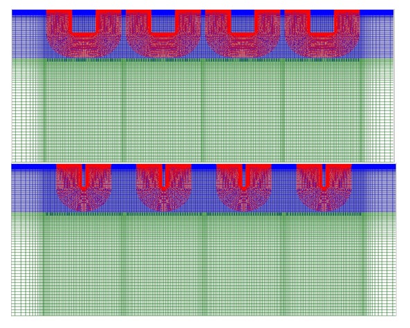
Here it is necessary to dwell in more detail on the specific features characteristic of periodic boundary conditions. Periodic boundary conditions lead to a more optimal construction of the pipe mesh (Figure 1). (In all the figures in the upper figure, for comparison, other things being equal, the turbulators are shown in cross-section in the form of a rib, and in the lower one - square). The pipe is split into several sections with a turbulator located in the middle and smooth inlet and outlet sections (see Figure 1).
In a periodic setting, only one section is considered, while in the general case it is necessary to use several sections (in [3, 4, 5, 6, 7, 8, 9, 11, 12, 13], the number of sections reached 12). To reduce the number of design nodes in the pipe, a more detailed near-wall area (blue mesh) and a less detailed axial area (green) are highlighted. In this case, the degree of detail changes, both in the longitudinal and in the circumferential directions (when using the three-dimensional case).
In addition, for a three-dimensional calculation in the axial region, a so-called. «patch» that removes unnecessary mesh thickening near the axis. The latter circumstance, all other things being equal, reduces the required number of calculation cells by about one and a half times (this circumstance becomes even more important in three- dimensional calculations).
The number of cells can be further reduced by applying periodic conditions along the longitudinal axis, since inlet and outlet sections are eliminated and one section is left. In terms of hydrodynamics, the periodic problem is posed as a problem with the preservation of a given mass flow rate calculated for a unit input velocity. In terms of heat transfer, depending on the selected boundary conditions for temperature, two options are possible. For isothermal walls, the problem is solved under the assumption that the mass- average temperature in the inlet section is constant.
In the second, the gradient of the average mass temperature is considered known, calculated from the value of the heat flow on the walls. Naturally, the inlet temperature is not recorded in this case. In addition to the periodic complete recording of the current state of the task, the program provides for the possibility of performing sample records with a given interval with their accumulation in a file, which is especially important for use in solving non- stationary tasks.
3. The main attention is paid to the local and integral characteristics of convective heat transfer, including the velocity components, hydraulic losses and heat transfer averaged over the selected area of the channel wall section, the results of calculations based on the turbulent characteristics of the terms of the equation for the energy of turbulent pulsations (generation, dissipation, convective and diffusion transfer). For the external flow around rectangular protrusions, a similar approach was applied, for example, in Ashrafian A [14]. The main direction of this work can be briefly characterized as follows: to carry out calculations of local and averaged parameters of flow and heat transfer in pipes with surface narrow turbulators in the form of a rib (s/h << 1; s is the width of the turbulizer, h is the height of the turbulizer) for relatively a wide range of channel geometry and coolant flow modes (Re = 104 ÷ 105; Pr = 0.72 ÷ 10; d/D = 0.98 ÷ 0.90; t/D = 0.25 ÷ 1.00); carry out an exhaustive analysis of the data obtained, focusing on the comparative analysis of the calculated data with the corresponding data for pipes with turbulators of square cross-section (s/h = 1), obtained in the framework of this work, as well as in Dreitser GA, Lobanov IE, Bystrov YuA, Ashrafian A [3, 4, 5, 6, 7, 8, 9, 11, 12, 13, 15, 16, 17], which were previously verified by the existing experiment [1, 2], as well as by data from other theoretical approaches [6, 7, 8, 9]; the comparative analysis should reveal the advantages and disadvantages of the above-mentioned narrow and wide turbulators, all other things being equal.
Research Problem Statement
It can be stated that the structure of a turbulent flow in a pipe, in which it is required to intensify heat transfer, has to a certain extent been studied experimentally and theoretically, which necessitates a maximum increase in the intensity of turbulent pulsations in certain areas of the flow in which this will give the greatest intensification effect. In order to successfully use the separation zones, it is necessary to know the mechanism of their interaction with the main turbulent flow and the mechanism of processes in the separation zone itself. The above processes are quite complex.
Qualitatively, on the basis of experimental data, they have been studied to the extent that it is possible to purposefully use vortex zones in order to intensify heat transfer in pipes [1, 2]. The main goal of this study is a theoretical study of the above vortex zones for pipes with turbulators of square and semicircular cross-sections using the factorized finite- volume method (FKOM), which was successfully tested when calculating such flows in Dreitser GA [3, 4, 5, 6], where the main emphasis was made to calculate the averaged parameters of the intensified flow and heat transfer.
The paper considers the most typical cases of application of periodic surface-located turbulators of square and semicircular cross-sections in straight round pipes (object of research) [1, 2], namely: Pr = 0.72; Re = 104÷105; d / D = 0.94÷0.90; t / D = 0.25÷1.25 (D and d are the larger and smaller inner diameters of the pipe with turbulators, respectively; t is the pitch between the turbulators). The cross-section of a straight round pipe with transverse surface-located surface flow turbulators of square and semicircular cross-sections is shown in Figure 2.
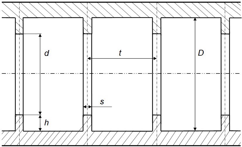
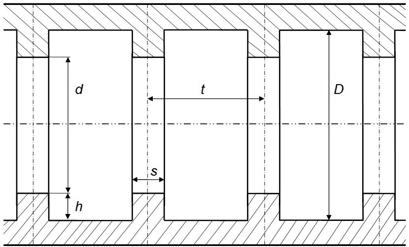
Square cross-section turbulators made of rectangular cross-section turbulators are most used to intensify heat transfer, since for turbulators of a different width, the patterns will be similar, except in extreme cases: too narrow turbulators will more turbulize the flow core than the wall layer, and for too wide turbulators there will be patterns. typical for pipes with transverse annular grooves.
For other cases of heat transfer intensification, the structure of the vortex zones will have a qualitatively similar character. Consequently, a comparison of the structures of vortex zones, all other things being equal, for turbulators of square and semicircular cross sections is the most optimal and indicative.
Calculated Local and Integral Characteristics of Flow and Heat Transfer in Pipes with A Cross-Section in the form of A Rib (S/H << 1)
Calculation of streamlines for pipes with transverse annular turbulators with a cross-section in the form of a rib (s/h << 1, where s is the width of the turbulator, is the height of the turbulator) for the considered range of determining parameters (Re = 104 ÷ 105; Pr = 0.72 ÷ 10; d/D = 0.95 ÷ 0.90; t/D = 0.25 ÷ 1.00) is based on the fact that earlier, as a result of carried out, for example in Lobanov IE [15, 16, 17, 18, 19, 20], numerical calculations were obtained local and integral characteristics of the flow and heat transfer in straight round tubes with semicircular and square turbulators with the corresponding streamlines.
Typical design flow lines for pipes with surface turbulesisators with cross sections in the form of a square (s / h = 1) and in the form of an edge (s / h = 0.15) for the above flow conditions are shown in Figures 3-5. The presented streamlines correlate well with the previously obtained values for pipes with turbulators, but for other conditions [1, 2, 3, 4, 5, 6, 12, 13, 15, 16, 17, 18, 19, 20]. As can be clearly seen in Figure 3-5, for pipes with fin-shaped turbulators with open cavities, there is a greater turbulization of the flow core than for turbulators in the form of a square, which causes an increase, first of all, of the hydraulic resistance and, to a small extent, of heat transfer, since the point of attachment from the turbulizer Figure 4-5.


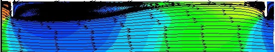

For closed cavities ( Figure 3), there is a decrease in the main vortex for turbulators in the form of a rib in relation to square turbulators, which leads to an increase in hydraulic resistance and, to a lesser extent, heat transfer. With an increase in the Reynolds number, the above effects become even more pronounced. Analyzing the presented in Figures 3-5 characteristic streamlines it can be noted that when passing from turbulators with a cross-section in the form of a square to a cross-section in the form of a rib, there is an increase in the local values of the hydraulic resistance with a noticeably smaller increase in the local parameters of heat transfer.
Consequently, the flow in pipes with narrow turbulators is qualitatively different in relation to wide turbulators (Figures 3-5), which determines the quantitative difference in the parameters of hydraulic resistance and heat transfer between them. The applied low-Reynolds computational model makes it possible to determine not only local, but also averaged flow and heat transfer parameters in channels with narrow transverse flow turbulators with a rib-shaped cross-section, therefore, within the framework of this work, the results of the latter were obtained for a fairly wide range of determining parameters: Re = 104 ÷ 105; Pr = 0.72 ÷ 10; d / D = 0.95 ÷ 0.90; t / D = 0.25–1.00, which is also typical for pipes with turbulators of semicircular (diaphragm) and rectangular cross-sections [1, 2, 3, 4, 5, 6, 12, 13, 15, 18, 19, 20].
The results of calculating the averaged parameters of heat transfer and hydraulicsIt is convenient to analyze the resistance in pipes with surface turbulators with a cross section in the form of a square (s/h = 1) and an edge (s/h << 1) for the above determining parameters in relative form - ξР/ξП, NuР/NuП (ξ - hydraulic resistance coefficient; Nu - Nusselt number; indices: «P» - rectangle, «P» - edge), - since it is possible to directly compare turbulators with different relative thickness (s/h) under equivalent conditions, to identify their advantages and disadvantages relative to each other.
The calculated data on heat transfer and hydraulic resistance obtained in the framework of this study using the low Reynolds model for conditions Re = 104; Pr = 0.72; d/D = 0.98 ÷ 0.90; t/D = 0.25 for turbulators in the form of a square and a rib with s/h = 0.15 showed that when passing from a square to a rib, both the hydraulic resistance and heat transfer increase: ξР/ξП = 101.5% ; NuР/NuП = 100.75% for low turbulators (d/D = 0.98) and ξР/ξП = 138.5%; NuР/NuП = 105.5% for high turbulators (d/D = 0.90).
For higher Reynolds numbers, all other things being equal (Re = 10five; Pr = 0.72; d/D = 0.98 ÷ 0.90; t/D = 0.25)
the corresponding data will be as follows: ξР/ξП = 109.0%; NuР/NuП = 104.3% for low turbulators (d/D = 0.98) and ξР/ ξП = 155.2%; NuР/NuП = 107.9% for high turbulators (d/D = 0.90). With an increase in the relative pitch between the turbulators to t/D = 0.50 under the conditions Re = 104; Pr = 0.72; d/D = 0.98 ÷ 0.90 the corresponding increases in the transition from square to edge are: ξР/ξП = 103.9%; NuР/ NuП = 100.9% for low turbulators (d/D = 0.98) and ξР/ξП = 120.9%; NuР/NuП = 105.3% for high turbulators (d/D = 0.90).
For relative pitch t/D= 0.50 and with higher Reynolds numbers, other things being equal (Re = 105; Pr = 0.72; d/D = 0.98÷0.90), the corresponding data will be: ξР/ξП = 107.1%; NuР/NuП = 105.9% for low turbulators (d/D = 0.98) and ξР/ ξП = 135.1%; NuР/NuП = 109.3% for high turbulators (d/D = 0.90). Further increase in the relative pitch between the turbulators t/D = 1.00 under the conditions Re = 104; Pr = 0.72; d/D = 0.98÷0.90 leads to the following corresponding increases in the parameters of heat transfer and hydraulic resistance: ξР / ξП = 101.1%; NuР / NuП = 100.6% for low turbulators (d/D = 0.98) and ξР/ξП = 122.6%; NuР/NuП = 111.5% for high turbulators (d/D = 0.90).
An increase in the Reynolds number to Re = 105 for a large relative pitch between the turbulators results in Pr = 0.72; d / D = 0.98 ÷ 0.90 to the following values of the relative parameters of heat transfer and hydraulic resistance: ξР / ξП = 104.0%; NuР / NuП = 101.6% for low turbulators (d/D = 0.98) and ξР/ξП = 112.7%; NuР / NuП = 105.0% for high turbulators (d/D = 0.90).
Hence, the maximum increase in the hydraulic resistance ξР/ξП takes place for small steps between the turbulators (t/D = 0.25), and the maximum increase in heat transfer- for large steps between the turbulators (t/D = 1.00). The increase in the heat transfer parameter - hydraulic resistance [(ξР/ξП) / (NuР/NuП)] for small steps between turbulators (t/D = 0.25) is about 1.3 ÷ 1.45, for medium steps (t/D = 0 , 50) - about 1.15 ÷ 1.25, for large (t/D = 1.00) - about 1.10 ÷ 1.07. Consequently, the optimal increase in the intensification of heat transfer during the transition from wide turbulators to narrow ones takes place at large steps between the turbulators.
The above calculated data was obtained for air. Pr = 0.72, therefore, in the future, similar data were obtained for large Reynolds numbers Pr = 10, all other things being equal, the analysis of which allows us to draw the following conclusions: a decrease in NuР / NuП values with an increase in the Prandtl number from 0.72 to 10 for relatively low turbulators (d/D = 0.98÷0.96) are about 1%; for relatively average (d/D = 0.95÷0.93) - about 2%; for relatively high (d/D = 0.92÷0.90) - about 6%.
Conclusions
1. In the study, the modeling of flow parameters and heat transfer in pipes with surface flow turbulators with a cross-section in the form of a rib was carried out (s/h << 1), as well as a square cross section (s/h = 1) based on multiblock computational technologies based on solving the factorized finite volume method (fkom) of the reynolds equations (closed using the menter shear stress transfer model) and energy equations (on multi- scale intersecting structured grids). 2. 2. Local and averaged parameters of flow and heat transfer in pipes with surface flow turbulators with a rib-like cross-section (s/h = 0.15) for a wide range of determining parameters (Re = 104 ÷ 105; Pr = 0.72 ÷ 10; d/D = 0.98 ÷ 0.90; t/D = 0.25 ÷ 1.00); for comparison, similar parameters were calculated for turbulators of square cross-section(s/h = 1). 3. 3. The calculated streamlines obtained for pipes with turbulators with a cross-section in the form of a rib (s/h = 0.15) are qualitatively different from similar streamlines for turbulators with a square cross-section (s/h = 1); the above causes a quantitative difference between the local and averaged parameters of hydraulic resistance. 4. It was found in the work that the maximum increase in hydraulic resistance ξР / ξП occurs for small steps between turbulators (t/D = 0.25), and the maximum increase in heat transfer - for large steps between turbulators (t/D = 1.00). 5. In the study, it was found that the optimal increase in the intensification of heat transfer during the transition from «square» turbulators to the rib takes place at large steps between the turbulators. 6. Calculated decrease in NuР/NuП values with increasing Prandtl number from small values (Pr = 0.72) to large (Pr = 10) for relatively low turbulators (d/D = 0.98÷0.96) are about 1%; for relatively average (d/D = 0.95÷0.93) - about 2%; for relatively high (d/D = 0.92÷0.90) - about 6%. 7. General analysis of the calculated data obtained in the study establishes that the use of tubes with turbulators with a cross-section in the form of a rib, compared with turbulators of a square cross-section, can be accompanied by a significant increase in hydraulic resistance with a relatively small increase in heat transfer.
References
-
Kalinin EK, Dreitser GA, Yarkho SA (1990) Intensification of heat transfer in the channels. Moscow, Mashinostroenie, pp: 208.
-
Kalinin EK, Dreitser GA, Korolev IZ, Kopp K (1998) Effective surfaces of heat exchange. Energoatomizdat, pp: 408.
-
Dreitser GA, Isaev SA, Lobanov IE (2003) Calculation of convective heat transfer in a pipe with periodic projections. Problems of Gas Dynamics and Heat and Mass Transfer in Power Plants: Proceedings of the XIV School-Seminar for Young Scientists and Specialists under the leadership of Academician. Moscow, MEI, Volume 1: 57-60.
-
Dreitser GA, Isaev SA, Lobanov IE (2004) Calculation of convective heat transfer in a pipe with periodic protrusions. Vestnik MAI 11(2): 28-35.
-
Dreitser GA, Isaev SA, Lobanov IE (2005) Calculation of convective heat transfer in a pipe with periodically located surface flow turbulators. High Temperature Thermal Physics 43(2): 223-230.
-
Lobanov IE (2005) Mathematical modeling of intensified heat transfer in turbulent flow in channels. Diss doct tech sciences, MAI, pp: 632.
-
Lobanov IE, Stein LM (2009) Mathematical modeling of intensified heat transfer during turbulent flow in channels using basic analytical and numerical methods. In: Vuzov S (Ed.), Promising heat exchangers with intensified heat exchange for metallurgical production (General theory of intensified heat transfer for heat exchangers used in modern metallurgical production). Volume 1, Publishing house of the Association of building universities, Moscow, Russia, pp: 405.
-
Lobanov IE, Stein LM (2010) Mathematical modeling of intensified heat transfer during turbulent flow in channels using non-basic analytical and numerical methods. In: Vuzov S (Ed.), Promising heat exchangers with intensified heat exchange for metallurgical production (General theory of intensified heat transfer for heat exchangers used in modern metallurgical production). Volume 2, Publishing house of the Association of building universities, Russia, pp: 290.
-
Lobanov IE, Stein LM (2010) Mathematical modeling of intensified heat transfer during turbulent flow in channels using multi-layer, super-multilayer and compound models of a turbulent boundary layer. In**:** Vuzov S (Ed.), Promising heat exchangers with intensified heat exchange for metallurgical production (General theory of intensified heat transfer for heat exchangers used in modern metallurgical production) Volume 3, MGAKHiS, Russia, pp: 288.
-
Bystrov YuA, Isaev SA, Kudryavtsev NA, Leontiev AI (2005) Numerical modeling of vortex intensification of heat transfer in pipe packs. Saint Petersburg, Shipbuilding, pp: 398.
-
Lobanov IE, Stein LM (2011) Special aspects of mathematical modeling of fluid dynamics, heat transfer, and heat transfer in heat exchangers with intensified heat transfer. In**:** Vuzov S (Ed.), Promising heat exchangers with intensified heat exchange for metallurgical production (General theory of intensified heat transfer for heat exchangers used in modern metallurgical production). In Volume 4, MGAKHiS, Russia, pp: 343.
-
Lobanov IE (2011) Theoretical study of the structure of vortex zones between periodic, superficially located flow turbulators of rectangular cross section. Izvestiya vuzov, Aviation technology, 4: 64-66.
-
Lobanov IE, Kalinin EK (2011) Theoretical research, comparison with experiment of streamlines and components of kinetic energy of turbulent pulsations in vortex structures in tubes with turbulators. Branch aspects of technical sciences 12: S4-S15.
-
Ashrafian A, Andersson HI (2003) Roughness Effects in Turbulent Channel Flow. Turbulence, Heat Transfer and Mass Transfer 4. Begell House Inc., New York, Wellington (UK), pp: 425-432.
-
Lobanov IE (2012) Mathematical modeling of the structure of vortex zones between periodic surface- located flow turbulators of a semicircular and square cross-section. Branch aspects of technical sciences 9: 11- 30.
-
Lobanov IE (2013) Theoretical study of the kinetic energy of turbulent pulsations and its components in pipes with turbulators. Moscow Scientific Review 1: 23- 30.
-
Lobanov IE (2013) Mathematical modeling of heat transfer in pipes with turbulators, as well as in rough pipes, in air at high Reynolds numbers. Branch aspects of technical sciences 9: 8-18.
-
Lobanov IE (2011) Modeling of intensified heat exchange in pipes with relatively high turbulators. Vestnik mashinostroeniya 3: S25-S33.
-
Lobanov IE (2012) Modeling the structure of vortex zones between periodic surface-located turbulators of a rectangular cross-section flow. Mathematical modeling 24(7): 45-58.
-
Lobanov IE (2013) Mathematical modeling of the dynamics of the development of vortex structures in tubes with turbulators. Moscow Scientific Review 12: 9-15.
- Sense, Gravity, Parity & Chirality in Mathematical Physics
- Quantum Lattice Simulations PHYSICS: Microcircuit Particle Formation and Observable Macroscopic Irreversible Time - A Discrete Lagrangian with Cellular Automata Framework
- Quantum Biology from Biomacromolecule to Cell, and Central Dogma Described by Quantum Theory
- Focus, Agility, Speed and Technology (FAST) for Sustainability and Growth
- Square Root Metric Geometry and Pati-Salam Model in Curved Space-Time
- A Simple System Demonstrating the Mpemba Effect in Classical Mechanics