Evaluation of 3DCT & MPR in Diagnosis of Craniofacial Fractures in Sudanese Population
Aims: To determine sensitivity of three-dimensional computed tomography and multiplanar reconstruction in imaging cranifacial fractures in khartoum state 2017. Methodology: Descriptive, analytical study, were done to show the visualization of craniofacial fracture in 3D and MPR CT imaging in 100 traumatic Sudanese patients. CT images were acquired using, sagittal, coronal, axial views of the craniofacial bone, the following area and site of the fracture were visualized. Data statistical analyzed were conducted using statistical package for social sciences SPSS (version 16). Result: 3D-CT scan represented sensitivity of 81.7% of visible craniofacial fractures and 18.3% of non visible craniofacial fractures respectively. MPR on the other hand had a superior sensitivity of a 100% over 3D which was of 81.7%. MPR and 3D both showed a high specificity and sensitivity in diagnosing craniofacial fractures.
Introduction
A CT scan makes use of computer-processed combinations of many X-ray images taken from different angles to produce cross-sectional (tomographic) images (virtual"slices") of specific areas of a scanned object, allowing the user to see inside the object without cutting [1]. The process of 3D imaging began with image acquisition protocols, which were optimized for subsequent post-processing. We have taken the step of identifying certain CT protocols that would always require 3D analysis and modified these protocols so that 3D imaging is an integral part of these studies. Referring physicians ordering these examinations now understand that they are simultaneously requesting additional 3D analysis. However, there are certain studies in which 3D imaging does not appear important prior to imaging the patient, but on reviewing axial images the radiologist may feel that 3D reconstruction may offer a problem solving option. In these situations, it is preferable to reconstruct the volumetric helical data in thinner sections and use this data for appropriate 3D reconstructions [2].
Based on the standardized protocols, the technologists in the 3D laboratory apply the appropriate 3D rendering software to create a data set of 3D images that is returned to the Picture Archiving Communications System (PACS) associated with the source images. Development of close communication between physicians and 3D technologists and close proximity of the 3D laboratory to the CT interpretation area allows radiologists to participate in 3D reconstruction with the technologists. In addition to 3D renderings there are a number of applications, which require quantitative measurements. These include planning prior to aortic stent graft placement or volumetric analysis prior to liver resection and living related organ donation [2, 3, 4, 5, 6, 7].
**Fracture of Skull**
Cranial Fractures
The majority of skull fractures result from blunt force or penetrating trauma, and can produce numerous signs and symptoms. The clinical features may be obvious, such as visible injuries and bleeding. There are also subtle signs of fracture, such as clear fluid draining from the ears and nose (cerebrospinal fluid leak indicative of base of skull fracture), poor balance and confusion, slurred speech and a stiff neck [8].
There are certain areas of the skull that are natural points of weakness:
- The Pterion: a ‘H-shaped’ junction between temporal, parietal, frontal and sphenoid bones. The thinnest part of the skull. A fracture here can lacerate an underlying artery (the middle meningeal artery), resulting in a extradural haematoma [8].
- Anterior Cranial Fossa: Depression of skull formed by frontal, ethmoid and sphenoid bones [8].
- Middle Cranial Fossa: Depression formed by sphenoid, temporal and parietal bones [8].
- Posterior Cranial Fossa: Depression formed by squamous and mastoid temporal bone, plus occipital bone [8].
Types of Fractures
There are four major types of cranial fracture
Depressed: A fracture of the bone with depression of the bone inwards. They occur as a result of a direct blow, causing skull indentation, with possible underlying brain injury [9].
Linear: The simple break in the bone, traversing its full thickness. They have radiating (stellate) fracture lines away from the point of impact. The most common type of cranial fracture [9].
Basal Skull: Affects the base of the skull. They characteristically present with bruising behind the ears, known as Battle’s sign (mastoid ecchymosis) or bruising around the eyes/orbits, known as Raccoon eye’s [9].
Diastatic: A fracture that occurs along a suture line, causing a widening of the suture. They are most often seen in children [9].
Facial Fractures
Facial fractures are common and generally trauma related, i.e. road traffic collisions, fights and falls. They are often associated with clinical features such as profuse bleeding, swelling, deformity and anaesthesia of the skin. The nasal bones are most frequently fractured, due to their prominent position at the bridge of the nose [10].
A maxillofacial fracture is one that affects the maxillae bones. This requires a trauma with a large amount of force. Facial fractures affecting the maxillary bones can be identified using the Le Fort classification, depending on the bones involved, ranging from 1 to 3 (most serious) [10].
**Methodology**
**CT technique of craniofacial imaging**
Patient position: The patient lies supine on the examination couch with their head within the head holder. The head is adjusted so that the enter - papillary line is pararal to the couch and the head is straight. The patient is positioned so that the longitudinal alignment light lies in the midline, and the horizontal alignment light passes through the nasion. Straps and foam pads are used for immobilization.
Equipment
- head holder
- immobilization foam pads
**Data collection tools and techniques**
All data was collected from traumatic patients referred for craniofacial CT examination, from all Sudanese subjects examined in the department of radiology in yastbshroon hospital (Khartoum, sudan) by selection randomly.
CT machine used for data collection TOSHIBA 16 slices.
**Methods of measurements**
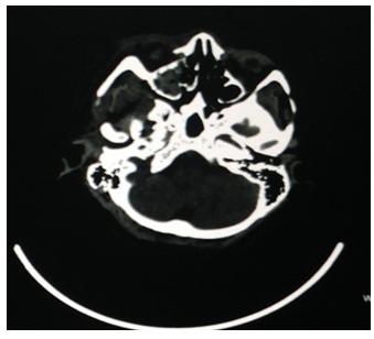
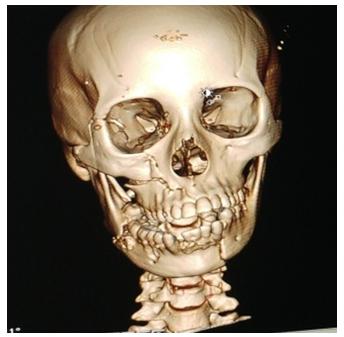
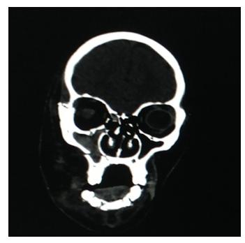
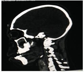
Fractures were visualized under (sagittal, axial and coronal) MPR and 3D images (Figures 1-4)
Results
Descriptive Statistics
The study was carried out on 60 patients with craniofacial fractures who were submitted to multislice CT scan and analyzed respectively (Figures 5 & 6). We interpreted and analyzed the images based on 7 protocols which are 1; Temporal with a total number of 8 visible fractures, 5 viewed by coronal and axial planes and 2 viewed by axial plane and 1 viewed by axial and sagittal planes. 2; parietal with a total number of 7 visible fractures, 5 viewed by sagittal and coronal planes, 1 viewed by axial coronal and sagittal planes, and 1 viewed by axial and sagittal planes. 3; Frontal with a total number of 6 visible fractures, 2 viewed by axial and sagittal planes, 2 viewed by axial plane, coronal and sagittal planes, 1 viewed by axial plane and 1 viewed by sagittal and coronal planes. 4; Occipital with a total number of 6 visible fracture, 4 viewed by axial and sagittal planes, and 2 viewed by axial and coronal planes. 5; Facial with a total number of 17 visible fractures, 7 viewed by axial coronal and sagittal planes, 5 viewed by axial and sagittal planes, 2 viewed by sagittal and coronal planes, 1 viewed by axial and coronal planes, 1 viewed by axial plane and 1 viewed by sagittal plane. 6; Base of the skull with a total number of 9 visible fractures which were all viewed by axial plane only. 7; Multiple fractures with a total number of 7 visible fractures all viewed by axial coronal and sagittal planes only 2 tempromandibular fractures and 5 facial/base of the skull. As shown in Table 1.
| Bone * MPR Cross Tabulation / Count | |||||||
|---|---|---|---|---|---|---|---|
| MPR | |||||||
| Axial | Sagittal | Axial & Sagittal | Axial, Coronal | Sagittal, Coronal | Axial, Sagittal, Coronal | Total | |
| Bone Temporal | 2 | 0 | 1 | 5 | 0 | 0 | 8 |
| Parietal | 0 | 0 | 1 | 0 | 5 | 1 | 7 |
| Frontal | 1 | 0 | 2 | 0 | 1 | 2 | 6 |
| Occipital | 0 | 0 | 4 | 2 | 0 | 0 | 6 |
| Facial | 1 | 1 | 5 | 1 | 2 | 7 | 17 |
| Base of skull | 9 | 0 | 0 | 0 | 0 | 0 | 9 |
| tem, Parital | 0 | 0 | 0 | 0 | 0 | 2 | 2 |
| facial, baseskull | 0 | 0 | 0 | 0 | 0 | 5 | 5 |
| Total | 13 | 1 | 13 | 8 | 8 | 17 | 60 |
Table 1: Shows the statistics for MPR distribution.
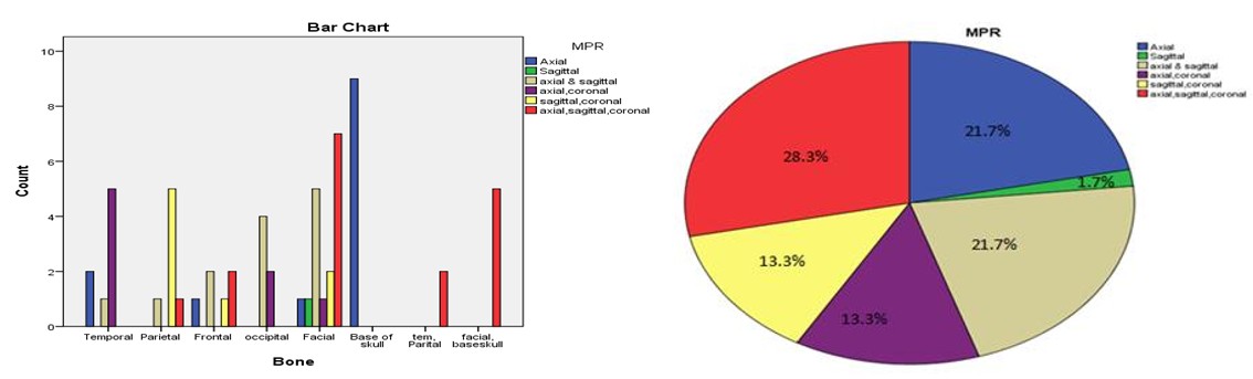
| MPR | ||||
| Frequency | Percent | Valid Percent | Cumulative Percent | |
| Valid Axial | 13 | 21.7 | 21.7 | 21.7 |
| Sagittal | 1 | 1.7 | 1.7 | 23.3 |
| axial & sagittal | 13 | 21.7 | 21.7 | 45 |
| axial,coronal | 8 | 13.3 | 13.3 | 58.3 |
| sagittal,coronal | 8 | 13.3 | 13.3 | 71.7 |
| axial,sagittal,coronal | 17 | 28.3 | 28.3 | 100 |
| Total | 60 | 100 | 100 |
Table 2: The statistic of validity test.
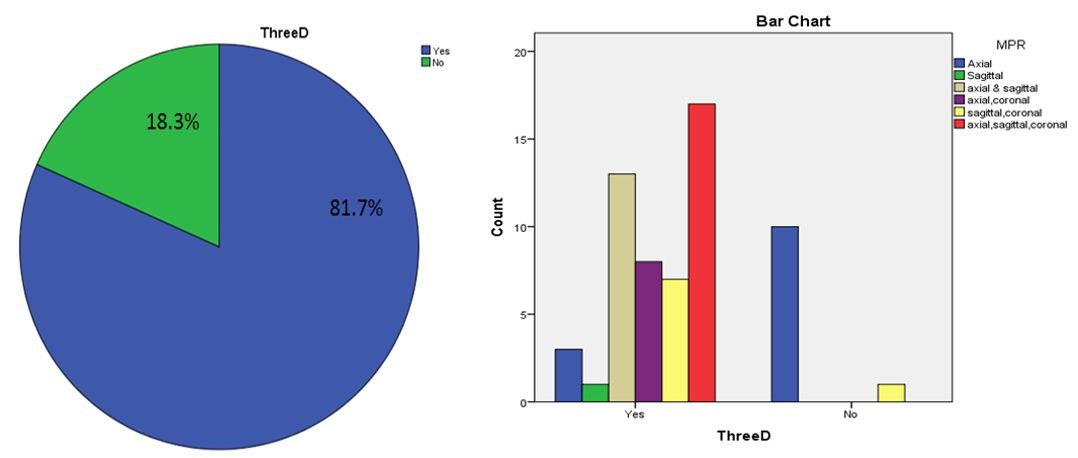
Table 2: The statistic of validity test. 3D-CT scan represented sensitivity of 81.7% of visible craniofacial fractures and 18.3% of non visible craniofacial fractures respectively. MPR on the other hand had a superior sensitivity of a 100% over 3D which was of 81.7%. MPR and 3D both showed a high specificity and sensitivity in diagnosing craniofacial fractures. As shown in Table 3.
| Frequency | Percent | Valid Percent | Cumulative Percent | |||||||||||||
| Valid Yes | 49 | 81.7 | 81.7 | 81.7 | ||||||||||||
| No | 11 | 18.3 | 18.3 | 100.0 | ||||||||||||
| Total | 60 | 100.0 | 100.0 |
Table 3: Shows the sensitivity of 3D image.
Discussion
From a previous study conducted by Denise Takehana dos Santos, Adriana Paula Andrade, Costa e Silva, Michael Walter Vannier (2004). 3D-CT scanning presented sensitivity of 78.9%, which was not superior to that of MPR (84.0%), axial/MPR/3D (90.5%) and coronal images (86.1%). While in our study, 3D-CT scan represented sensitivity of 81.7% of visible craniofacial fractures and 18.3% of non visible craniofacial fractures respectively. MPR on the other hand had a superior sensitivity of a 100% over 3D which was of 81.7%.
Conclusion
3D was sensitive in diagnosing craniofacial fractures whereby most fractures were visible except for mostly base of the skull which was not visible. Temporal was best viewed by coronal an axial planes, parietal was best viewed by sagittal and coronal planes, frontal was best viewed by axial coronal and sagittal planes, occipital was best viewed by axial and sagittal planes, facial was best viewed by axial, coronal and sagittal planes, base of the skull was only viewed by axial plane, multiple fractures were only viewed by axial, coronal and sagittal planes. MPR had a superior sensitivity of a 100% over 3D which was of 81.7%.
Recommendations
- Use a large sample size/number for better evaluation
- Specification of type of fracture needed for the study will be better for easy evaluation.
- Specification of bone under study will ease up findings and data acquisition.
References
-
Herman, Gabor T (2009) Fundamentals of computerized tomography: Image reconstruction from projection, 2nd (Edn.), Springer.
-
Heath DG, Soyer PA, Kuszyk BS, Bliss DF, Calhoun PS, et al. (1995) Three-dimensional spiral CT during arterial portography: comparison of three rendering techniques. Radiographics 15(4): 1001-1011.
-
Goh KY, Ahuja A, Walkden SB, Poon WS (1997) Is Rotine computed tomographic (CT) scanning necessary in suspected basal skull fractures? Injury 28(5-6): 353-357.
-
Connor SE, Flis C (2005) The contribution of high resolution multiplanar reformats of the skull base to the detection of skull-base fractures. Clin Radiol 60(8): 878–885.
-
CDC, Injury prevention and control: traumatic brain injury. Centers for Disease Control and Prevention, US.
-
Derkowski W, Kedzia A, Glonek M (2003) Clinical anatomy of the human anterior cranial fossa during the prenatal period. Folia Morphol 62(3): 271-273.
-
Schlossberg L, Zuidema GD (1997) The Johns Hopkins Atlas of Human Functional Anatomy 4th (edn), Johns Hopkins University Press, pp: 16.
-
Johannes, Lang (1999) Skull base and related structures: atlas of clinical anatomy 2nd (Edn.), Schattauer, London.
-
Singh J, Stock A (2006) Head Trauma. Emedicine com.
-
Altobelli DE, Kikinis R, Mulliken JB, Cline H, Lorensen W, et al. (1993) Computer-assisted three-dimensional planning in craniofacial surgery. Plast Reconstr Surg 92(4): 576-585.
- Ultrasound Guided Therapeutic Nerve Blocks
- Cyclops Lesion Without ACL Reconstruction: A Rare Case in a Patient with Intact Anterior Cruciate Ligament and Tibial Plateau Fracture
- Dosimetric Comparison between Two Dose Calculation Algorithms in SBRT Treatment of Lung Cancer in Ring-based and C-arm Radiation Therapy Equipment
- Adolescent Testicular Adrenal Rest Tumors: A Case Report and Review of the Literature
- Giant Intrathoracic Lipoma: A Rare Presentation
- Image of a Right Renal Angiomyolipoma Complicated by Hemorrhage