A MIP-based 3D Contour Technique for Radiosurgery of Arteriovenous Malformation
Purpose: Traditional, orthogonal digital subtraction angiography (DSA) has been the gold standard in the diagnosis of Arteriovenous Malformation (AVM) and in nidus delineation for its treatment using stereotactic radiosurgery (SRS), notably with the GammaKnife. The progressively advanced Time-evolved, CTA, MRA and rotational angiography that are capable of accounting for haemodynamic features of AVM have made them attractive alternatives. However, the maximum intensity projection (MIP) that is a frequent tool in AVM analysis has not been easily integrated with most treatment planning systems. Herein, a novel technique is presented that allows conversion of the MIP images of the nidus to axial images. As such, contours of the AVM nidus can be established more accurately for SRS treatment when DSA is not available. Methods: In the proposed method, the AVM nidus delineated on the MIPs from multiple projection angels are back-projected to obtain a “reconstructed” 3D AVM nidus volume. Adjusting the threshold accordingly, the nidus border can then be reconstructed and transcribed onto the axial images. Results: The method was tested on a digital phantom with an artificial AVM volume, as well as on a patient MRA data set containing a real AVM. The reconstructed AVM contours, when compared to that of direct delineation from axial images, show satisfactory agreement in both phantom and in a clinical example. Conclusions: Using MIP from 4D MRA or CTA to facilitate AVM nidus delineations demonstrates both technical feasibility and potential clinical advantages for SRS of AVM.
Introduction
Arteriovenous malformation (AVM) is an irregular connection bypassing the capillary system, directly diverting blood from the arteries to the veins. AVM can occur in any location, but it is most commonly found in the brain and spine. Most AVMs could be asymptomatic. However, a cerebral AVM may cause haemorrhages, headaches, epileptic seizures or difficulties with movement coordination [1, 2]. About half of AVM cases were diagnosed through incidental findings, while the half were due to onsets of complications. There are different types of treatments available for AVM, such as conventional microsurgery, endovascular embolization, and stereotactic radiosurgery [3, 4]. Conventional surgery is not recommended for high- risk or deep brain regions, which may cause haemorrhages or seizures. Endovascular embolization is usually applied as an adjunct to surgical resection or stereotactic radiosurgery (SRS). Among them, radiosurgery is the most appropriate alternative for small AVMs in an area where they are difficult for surgical operation or restricted by using other treatments [5, 6, 7, 8].
Stereotactic radiosurgery, having successfully treated AVM for years, delivers high-dose of radiation to induce a series of histopathological responses and eventually obliterate the AVM nidus. Although biological dose response and clinical effects are different, the SRS treatment planning for AVM usually follows the procedure used for malignancies [9, 10, 11]. An important step for radiosurgery planning is to delineate AVM nidus on one or multiple types of imaging modalities. Traditionally, starting from GammaKnife, bi- planar DSA has been the gold standard for nidus delineation. The progressive advances in the development of 4D CT angiography and MR angiography using Time-of-flight or Time-evolved technique has made haemodynamic features of AVM accessible [12, 13, 14, 15, 16, 17], and prompted the rapid application of 4D MRA and CTA in the treatment planning for AVM target delineation [18, 19]. DSA images used to define the AVM nidus are orthogonal 2D volume projections [20, 21]. The contours of AVM nidus delineated from the DSA projections are co- registered onto the conventional MRI or CT axial images for dose computation [22, 23].
While 4D MRA and CTA are gaining wider application, DSA continues to be used in the Gamma Knife planning system. However, DSA contouring features are not available in most of the other SRS planning and delivery systems. Additionally, when using 4D MRA or CTA, AVM nidus is delineated exclusively on axial images in all commercially available treatment planning systems.
Due to the uniquely intricate architecture of AVM, volumetric projections continue to be an indispensible method of evaluating and determining the nidus. A study demonstrated that the targeted AVM delineated on MRA (axial images) are larger than those delineated on DSA [24]. Another study found that substantial inter-observer variations exist when contouring brain AVMs on DSA [20]. To extend the capacity of traditional DSA, 3D rotational angiography (3DRA), or Time-resolved DSA has been an active on-going technical development to obtain multi- angular volumetric projections. The 3DRA was then even recommended by some studies as the new gold standard, to improve the accuracy and consistency of AVM contouring [25, 26]. Consistent with such perspective, in any current commercial 4D MRA and CTA system, volumetric projection in the form of Maximum-Intensity Projection (MIP) has always been available as an integral part of analytical “tool-box” and has been under continuous improvement [19, 27, 28]. This suggests logical advantages of combining thin sectional images with MIPs when using 4D MRA or CTA to describe an AVM, and has motivated the development of a tool that can effectively utilize MIPs from MRA or CTA and incorporate them into SRS planning. The method and the software described in this technical note will allow the use of MIP images from MRA or CTA to facilitate more accurate delineation of AVM nidus in the axial images that are compatible with all treatment planning systems.
Methods and Materials
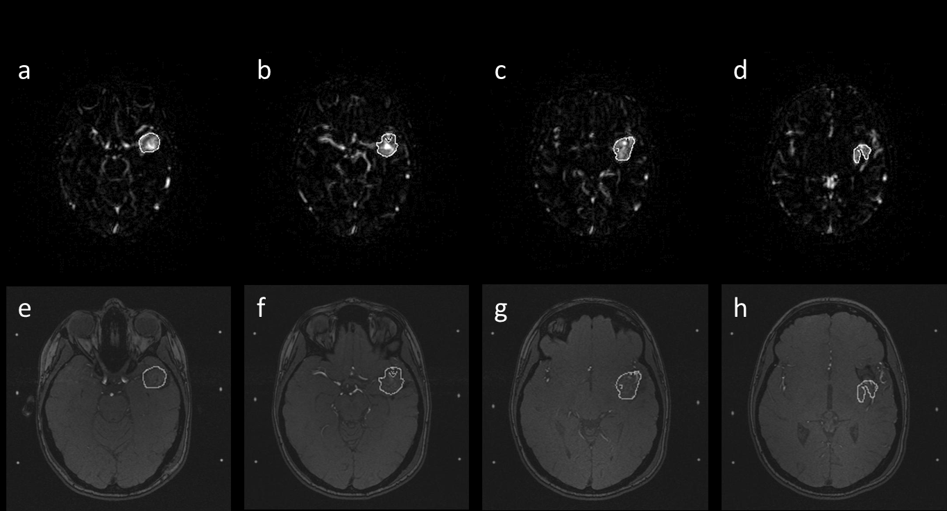
In this report, an MRA image set containing an AVM was used to demonstrate the developed method.
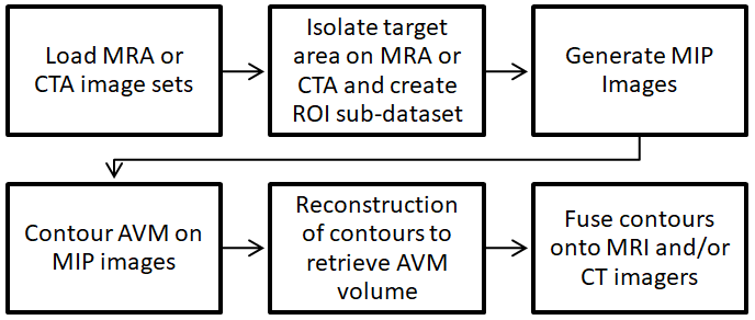
Following conventional definitions, we define the system of coordinates as the following: the X-axis represents medial/lateral direction; the Y-axis, anterior/posterior direction; and the Z-axis, superior/inferior direction. As aforementioned, the key objective of this method is to delineate AVM on the MIP images and then transcribe to the sectional (for example, axial) images. To focus on the AVM nidus, the volume containing AVM is isolated first to form an AVM sub-dataset and used to generate MIP images. The number of projections can be user-defined. On each MIP image, the AVM nidus is delineated. After obtaining contours on all MIP images, back-projections are performed to generate a new 3D dataset that contains AVM information. This new dataset is then processed by section to delineate the region of back-projected intersections, forming the reconstructed region of AVM nidus. The region of the AVM nidus is then co-registered with the MRI and/ or CT images for dose planning. Figure 1 illustrates the procedure of this MIP-based AVM contouring method.
Technical details are described by the following step-by-step procedure
Creating MRA Sub-Dataset
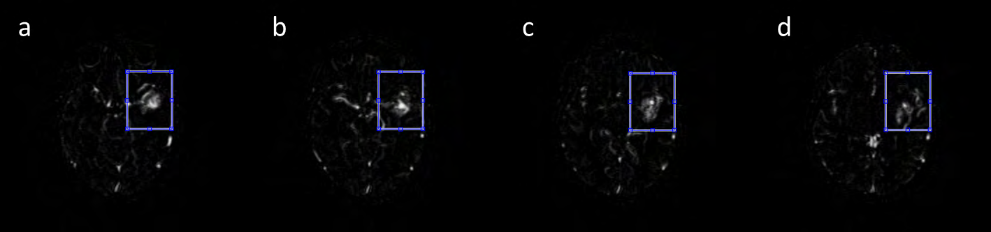
In order to eliminate the irrelevant image content, the AVM volume is first isolated by drawing a rectangular ROI on a MRA axial image, sufficiently large to enclose the whole AVM. The ROI is then extended to include all MRA axial images. All voxels outside of the rectangular cuboid are then removed to form a new 3D dataset, called AVM sub-volume (Figure 2). The AVM sub-volume has the same coordinates (x,y,z) as the raw MRA dataset.
3D Projection of AVM on MIP Images
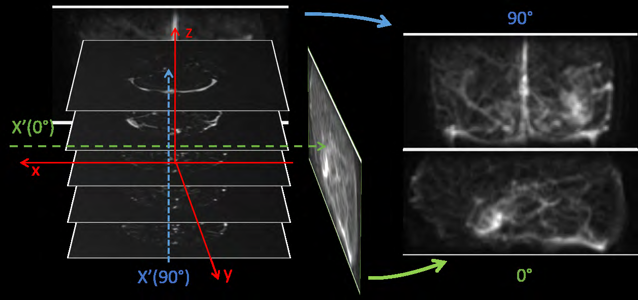
By creating maximum intensity projection or MIP images, perpendicular to the z-axis, projected AVM volume can be visualized. Figure 3 shows the MIPs projection angles around the x-axis from 0° and 90°, respectively. Each MIP is a 2D image, representing composite 3D projection perpendicular to the z-axis. The developed method allows the user to select the number (N) of projections with specified angular intervals. Because the projections are centrosymmetric, the projection angles range from 0° to 180°. For example, if N = 10, then θ = 0°, 18°, 36°, 54°, 72°, 90°, 108°, 126°, 144°, and 162°, and 10 MIPs will be generated. In this dataset, called MIP angiogram, each MIP image is on a projected x’-z plane defined by the coordinates (x’,z,θ), with .
Delineation of AVM on MIP Angiogram
Following the generation of the MIP Angiogram, the AVM nidus can be delineated (Figure 4). Since the MIP images can be generated from multiple arbitrary angles, one can always chose the projections in which the AVM nidus can be better appreciated. Subsequently, another new dataset, with the same coordinate of (x’,z,θ) as the MIP angiogram, will be generated, called the AVM projection-contour volume.

Reconstruction of AVM Volume from MIP Projections
As most TPSs (Treatment planning systems) cannot use MIP angiograms (AVM projection-contours) for planning and dose computation, the contoured AVM nidus on the MIPs has to be transcribed to the sectional images. From the MIP AVM contour dataset (x’,z,θ), we can obtain a 3D volume matrix by performing Radon-equivalent transformations along all z positions. The axial AVM contours can be reconstructed from the newly created 3D volume matrix that contains the AVM volume computed from the intersection of back projected MIP AVM contours.
Fusion of AVM Volume
The final step is to co-register or fuse the reconstructed AVM contour with the planning MRI or CT.
Since the AVM volume is defined in the same coordinates as the MRA dataset and the AVM projection-volume is centrosymmetric, the reconstructed contours can be easily registered to MRA scans. A user-adjustable thresholding tool is provided to modify the shape of the reconstructed contour so as to optimize the delineation process. Through this fusion or co-registration process, MIP-based AVM contours are subsequently transcribed to all image sets. Figure 5 demonstrates the reconstruction process.
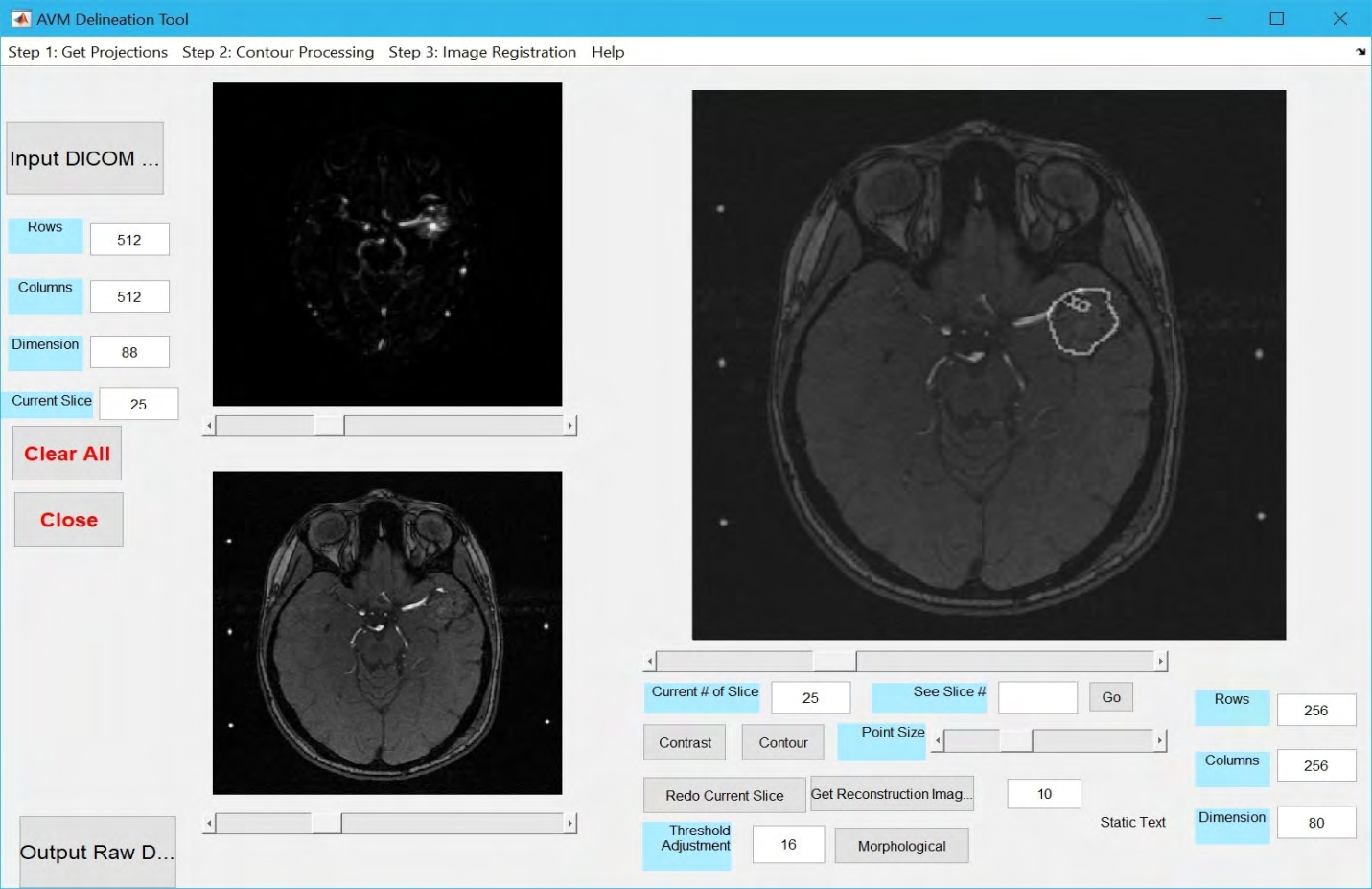
GUI Design and Associated Tools
A GUI (graphical user interface) was developed to facilitate the aforedescribed procedures. The software was developed in the MatLab (Mathworks, MA) environment and converted into a standalone application that can be executed on any operating system.
Results
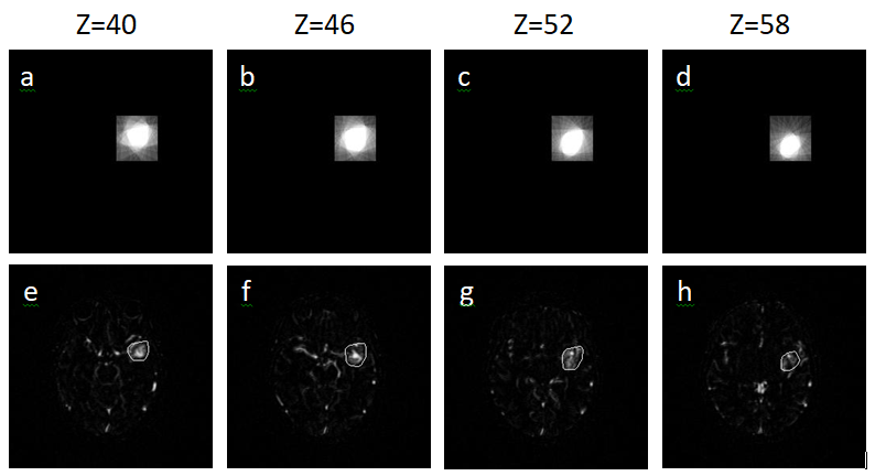
It is not in the scope of this report to discuss the best way to identify AVM nidus on MIPs of MRA or CTA. Rather we focus on the aim of transcribing a contour delineated on a set of MIPs to the raw sectional images. In order to quantitatively evaluate the method’s robustness, a digital phantom that mimics an AVM and surrounding tissues was generated to serve as the “ground truth”. Again, we assume all the clinically essential features including the hemodynamic information have been contained in the phantom dataset. The main goal is to determine the accuracy of geometric data processing. The digital phantom contains 256x256x256 voxels. Located within the 3D matrix, there is an ellipsoid- like object consisting of connected, semi-connected or disconnected clusters (variable high intensity pixels), surrounded by a randomly generated fiber-like background. Ovals on each slice were designed to be the same length/ width ratio 1:0.6875, which in the middle slice (z=127) shows a maximum size 2cm x 1.375cm. We performed the aforedescribed procedures and compared the reconstructed contours with that delineated directly from the raw dataset (ground truth): MIPs were generated from the raw phantom dataset; “AVM” contours were delineated from the MIP images; back projection was performed to create a new 3D dataset with all MIP-based AVM contours intersected; The sectional contours were reconstructed, fused and transcribed onto the original axial images (Figure 8). Five settings were used to run the test with the number of MIP projection set to 5, 10, 15, 20 and 26. The test on each projection setting was performed three times each time by a different physicist.
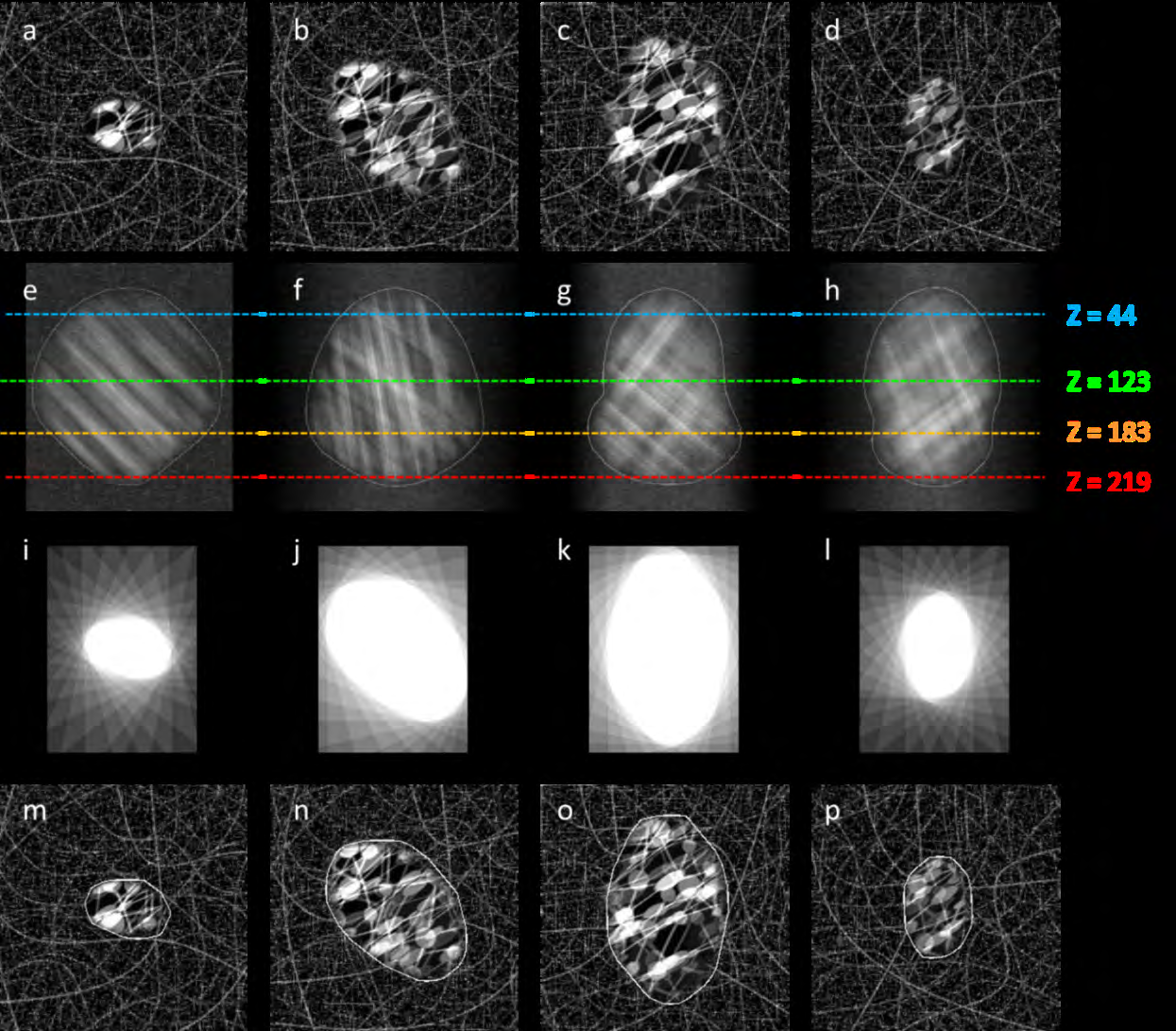
Figure 8: Top row: Slices of designed phantom at different levels (the x-y plane images); Second row: Projections of the phantom from different angles (the MIP images), delineations were performed by an operator; Third row: Back projection of lines from the MIP images, the region formed by all intersections of the back projection indicates the shape of AVM; Forth row: Retrieved contours of the simulated AVM are superimposed on the original sectional images.
The quantitative evaluation of contour error was carried out by calculating average ‘radius’ difference between reconstructed contours and original ellipsoid-like object. ‘Radius’ is the distance between geometric center of ellipsoid- like object and any point on its surface. The total contour error is in turn defined by the compounded Average Radial Overestimation (ARO) and Average Radial Underestimation (ARU). The ARU is a measure of the underestimation of the radius. The ARU is computed in three planes going through the geometric center of the AVM: axial, sagittal, and coronal. The ARU is the average underestimation of the radius averaged over angle and sampled every degree. When the contoured radius is equal or larger than the true radius, the underestimation is zero. The ARO rate indicates overestimation and is measured in a similar way to the ARO rate. The ARO rate is computed in three planes going through the geometric center of the AVM: axial, sagittal, and coronal. The ARO rate is the average overestimation of the radius averaged over angle and sampled every degree. When the contoured radius is equal or smaller than the true radius, the overestimation is zero.
Table 1 shows the results from all test runs. In this phantom study, the contour errors range from 0.487±0.38mm (15 projection MIPs) to 0.816±0.38 mm (5 projection MIPs).
| Number of projections | Contour error (mm) | ARU (mm) | ARO (mm) |
|---|---|---|---|
| 5 | 0.816±0.28 | 0.478 | 0.29 |
| 10 | 0.622±0.26 | 0.328 | 0.269 |
| 15 | 0.487±0.28 | 0.239 | 0.234 |
| 20 | 0.655±0.50 | 0.206 | 0.433 |
| 26 | 0.795±0.35 | 0.157 | 0.622 |
Table 1: Contour error (Average Radial Underestimation and Average Radial Overestimation) of the AVM nidus volume, calculated by
Table 1: Contour error (Average Radial Underestimation and Average Radial Overestimation) of the AVM nidus volume, calculated by the percent difference between the ground truth “AVM nidus” volume and the volume enclosed by the retrieved ROI contours. For each of the five settings, the test was repeated three times each time with a different physicist.
Discussion
Based on the experiment’s results performed on the AVM digital phantom, sub-millimeter accuracy can be achieved with the described contouring technique. It is noted that the more projections, the lower rate of ARU contouring. In principle, large number of projections will eventually be able to reduce the rate of ARU to a negligible residue, i.e., back projection intersections “filling” in every voxel of the nidus. However, in addition to the burden of contouring many MIP images, more projections also induce higher rates of ARO contouring, i.e., back projection “smoothing” the surface of the nidus. A high ARO rate will damage normal tissues. Our experiments show that about 15 projections yield the minimum matching error. The delineations were conducted 3 times by a different physicist each time. The low standard deviations imply the reliability of the evaluation.
Conclusion
Although the MIP images from 4D MRA and CTA resemble conventional digital-subtraction angiograms and often offer important perspectives for visualizing AVM nidus, they are not readily usable by most of treatment planning systems for radiosurgery. The technique and software described in this paper allows AVM nidus to be contoured on the MRA or CTA MIPs and then conveniently transcribed onto axial images, ready to be imported by DICOM into any TPS for treatment planning. This may offer additional clinical advantages when projection views are crucial to appreciating the AVM nidus structure and the sectional images alone are insufficient.
Acknowledgements
Authors are grateful to the Innovative Cancer Institute (South Miami, Florida, USA) for providing MRA and MRI image data for this study.
Declarations
Yuwei Zhou, Yi Zheng, Brian Stuart, Weizhao Zhao, and Xiaodong Wu have no funding to declare.
Yuwei Zhou, Yi Zheng, Brian Stuart, Weizhao Zhao, and Xiaodong Wu declare that they have no conflict of interest.
Ethics approval: Not applicable
Consent to participate: Not applicable
Availability of data and material: Data would be available at the Department of Biomedical Engineering, University of Miami Code availability: Code was written with MatlabTM and is kept at the department of Biomedical Engineering, University of Miami
References
-
Stapf C, Mast H, Sciacca RR, Choi JH, Khaw AV, et al. (2006) Predictors of hemorrhage in patients with untreated brain arteriovenous malformation. Neurology 66(9): 1350-1355.
-
Hernesniemi JA, Dashti R, Juvela S, Väärt K, Niemelä M, et al. (2008) Natural history of brain arteriovenous malformations: a long-term follow-up study of risk of hemorrhage in 238 patients. Neurosurgery 63(5): 823- 831.
-
Brenner DJ, Martel MK, Hall EJ (1991) Fractionated regimens for stereotactic radiotherapy of recurrent tumors in the brain. Int J Radiat Oncol Biol Phys 21(3): 819-824.
-
Kondziolka D, Lunsford LD, Witt TC, Flickinger JC (2000) The future of radiosurgery: radiobiology, technology, and applications. Surg Neurol 54(6): 406-414.
-
Hall EJ, Brenner DJ (1993) The radiobiology of radiosurgery: rationale for different treatment regimes for AVMs and malignancies. Int J Radiat Oncol Biol Phys 25(2): 381-385.
-
ApSimon HT, Reef H, Phadke RV, Popovic EA (2002) A population-based study of brain arteriovenous malformation: long-term treatment outcomes. Stroke 33(12): 2794-2800.
-
Hillman J (2001) Population-based analysis of arteriovenous malformation treatment. J Neurosurg 95(4): 633-637.
-
Aoun RJN, Sattur MG, Krishna C, Gupta A, Welz ME, et al. (2017) Awake Surgery for Brain Vascular Malformations and Moyamoya Disease. World Neurosurg 105: 659-671.
-
Flickinger JC, Kondziolka D, Maitz AH, Lunsford LD (2002) An analysis of the dose-response for arteriovenous malformation radiosurgery and other factors affecting obliteration. Radiother Oncol 63(3): 347-354.
-
Pollock BE, Gorman DA, Coffey RJ (2003) Patient outcomes after arteriovenous malformation radiosurgical management: results based on a 5- to 14- year follow-up study. Neurosurgery 52(6): 1291-1297.
-
Shin M, Kawahara N, Maruyama K, Tago M, Ueki K, et al. (2005) Risk of hemorrhage from an arteriovenous malformation confirmed to have been obliterated on angiography after stereotactic radiosurgery. Journal of Neurosurgery 102(5): 842-846.
-
Bednarz G, Downes B, Werner Wasik M, Rosenwasser RH (2000) Combining stereotactic angiography and 3D time- of-flight magnetic resonance angiography in treatment planning for arteriovenous malformation radiosurgery. Int J Radiat Oncol Biol Phys 46(5): 1149-1154.
-
Griffiths PD, Hoggard N, Warren DJ, Wilkinson ID, Anderson B, et al. (2000) Brain arteriovenous malformations: assessment with dynamic MR digital subtraction angiography. AJNR Am J Neuroradiol 21(10): 1892-1899.
-
Warren DJ, Hoggard N, Walton L, Radatz MW, Kemeny AA, et al. (2001) Cerebral arteriovenous malformations: comparison of novel magnetic resonance angiographic techniques and conventional catheter angiography. Neurosurgery 48(5): 973-983.
-
Tanaka H, Numaguchi Y, Konno S, Shrier DA, Shibata DK, et al. (1997) Initial experience with helical CT and 3D reconstruction in therapeutic planning of cerebral AVMs: comparison with 3D time-of-flight MRA and digital subtraction angiography. J Comput Assist Tomogr 21(5): 811-817.
-
Salomon EJ, Barfett J, Willems PW, Geibprasert S, Bacigaluppi S, et al. (2009) Dynamic CT angiography and CT perfusion employing a 320-detector row CT: protocol and current clinical applications. Klin Neuroradiol 19(3): 187-196.
-
Yu S, Yan L, Yao Y, Wang S, Yang M, et al. (2012) Noncontrast dynamic MRA in intracranial arteriovenous malformation (AVM), comparison with time of flight (TOF) and digital subtraction angiography (DSA). Magn Reson Imaging 30(6): 869-877.
-
Cifarelli CP, Vargo JA, Tenenholz T, Hack JD, Guthrie G, et al. (2018) Gamma Knife Radiosurgery for Arteriovenous Malformations Using a Four-Dimensional Dynamic Volume Computed Tomography Angiography Planning System as an Alternative to Traditional Catheter Angiogram. Cureus 10(6): e2788.
-
Cheng YC, Chen HC, Wu CH, Wu YY, Sun MH, et al. (2016) Magnetic Resonance Angiography in the Diagnosis of Cerebral Arteriovenous Malformation and Dural Arteriovenous Fistulas: Comparison of Time- Resolved Magnetic Resonance Angiography and Three Dimensional Time-of-Flight Magnetic Resonance Angiography. Iran J Radiol 13(2): e19814.
-
Buis DR, Lagerwaard FJ, Barkhof F, Dirven CMF, Lycklama GJ, et al. (2005) Stereotactic radiosurgery for brain AVMs: role of interobserver variation in target definition on digital subtraction angiography. Int J Radiat Oncol Biol Phys 62(1): 246-252.
-
Chen KK, Guo WY, Yang HC, Lin CJ, Wu CHF, et al. (2017) Application of Time-Resolved 3D Digital Subtraction Angiography to Plan Cerebral Arteriovenous Malformation Radiosurgery. AJNR Am J Neuroradiol 38(4): 740-746.
-
Turner RC, Lucke Wold BP, Josiah D, Gonzalez J, Schmidt M, et al. (2016) Stereotactic radiosurgery planning based on time-resolved CTA for arteriovenous malformation: a case report and review of the literature. Acta Neurochir (Wien) 158(8): 1555-1562.
-
Steenbeke F, Gevaert T, Engels B, Poels K, D’Haens J, et al. (2014) Analysis of the targeting uncertainty of a stereotactic frameless radiosurgery technique for arteriovenous malformation. Radiother Oncol 113(3): 371-373.
-
Buis DR, Lagerwaard FJ, Dirven CM, Barkhof F, Knol DL, et al. (2007) Delineation of brain AVMs on MR-Angiography for the purpose of stereotactic radiosurgery. Int J Radiat Oncol Biol Phys 67(1): 308-316.
-
Li F, Chenoune Y, Ouenniche M, Blanc R, Petit E (2014) Segmentation and reconstruction of cerebral vessels from 3D rotational angiography for AVM embolization planning. Conf Proc IEEE Eng Med Biol Soc 2014: 5522- 5525.
-
Stancanello J, Cavedon C, Francescon P, Cerveri P, Ferrigno G, et al. (2004) Development and validation of a CT-3D rotational angiography registration method for AVM radiosurgery. Med Phys 31(6): 1363-1371.
-
Singh R, Gupta V, Ahuja C, Khandelwal N (2018) Time resolved computed tomography angiography in the evaluation of brain arteriovenous malformation: a feasibility study. Neuroradiol J 31(3): 230-234.
-
Kim JH, Yi JH, Chang CH, Jung YJ (2018) Evaluation of the Accuracy in Maximum Intensity Projection Images of Cerebral Computed Tomographic Angiography for the Diagnosis of Cerebral Vasospasm Following Subarachnoid Hemorrhage, in Comparison to Digital Subtraction Angiography. J Cerebrovasc Endovasc Neurosurg 20(1): 5-13.
- Ultrasound Guided Therapeutic Nerve Blocks
- Cyclops Lesion Without ACL Reconstruction: A Rare Case in a Patient with Intact Anterior Cruciate Ligament and Tibial Plateau Fracture
- Dosimetric Comparison between Two Dose Calculation Algorithms in SBRT Treatment of Lung Cancer in Ring-based and C-arm Radiation Therapy Equipment
- Adolescent Testicular Adrenal Rest Tumors: A Case Report and Review of the Literature
- Giant Intrathoracic Lipoma: A Rare Presentation
- Image of a Right Renal Angiomyolipoma Complicated by Hemorrhage