Analytical Optimization of Hydraulic Fracturing
Hydraulic fracturing optimization is a critical aspect of improving the recovery of unconventional shale formation. This paper discusses the use of different types of proppants, rate optimization, and proppant amount optimization to improve hydraulic fracturing techniques. The paper begins with a discussion of proppant selection, which is a critical aspect of hydraulic fracturing. The authors highlight the importance of proppant endurance in holding the fracture opening and provide a range of proppants suitable for different confining pressures. Tables and charts are included to illustrate the permeability values of various proppants under different closure stress values. This section also emphasizes the significance of proppant shape in creating a more conductive path in the fracture. The next section of the paper discusses the methodology used in the study, including the Fracpro software simulation parameters. The authors then delve into the optimization of proppant specific gravity and the results of their experiments with five different types of proppants. The paper highlights the impact of proppant specific gravity on fracture width and dimensionless conductivity (FCD). The author also focusses on the optimization of pumping rate, which is an essential parameter of hydraulic fracturing operations. The paper includes simulation studies conducted to determine the effects of pumping rate on fracture parameters such as propped length and propped height. The authors highlight the relationship between rate and FCD and how it is affected by permeability values of the proppant. Finally, the paper discusses proppant amount optimization, which is a critical point of hydraulic fracturing optimization. The authors provide an overview of the results of the experiments conducted to determine the optimal amount of proppant required for different hydraulic fracturing operations. Overall, this paper provides valuable insights for researchers and engineers working to improve hydraulic fracturing techniques for tight shales formation. The authors use a combination of theory, experiments, and charts to provide a comprehensive overview of the various aspects of hydraulic fracturing optimization.
Introduction
This article explores diverse facets of optimizing hydraulic fracturing for unconventional shale formations. The authors present a comprehensive examination of proppant types, rate optimization, and proppant quantity optimization employed in hydraulic fracturing procedures. The study details the methodology, incorporating Fracpro Simulation Parameters. Through a blend of theory, experiments, and charts, the authors offer valuable insights to researchers and engineers striving to enhance hydraulic fracturing methods for tight shale formations.
Proppant Selection
Proppant plays a crucial role in establishing a conductive pathway within the induced hydraulic fracture, extending from the wellbore to the surrounding formation. In the early stages of hydraulic fracturing operations, conventional proppants primarily consisted of sand. However, advancements in technology and the evolution of hydraulic fracturing practices have led to the utilization of more sophisticated proppant materials. Currently, coated sand and ceramic materials, varying in size and strength, have become prevalent choices in the industry. These modern proppant alternatives contribute to the optimization of hydraulic fracturing processes by enhancing conductivity and overall efficiency in facilitating the flow of hydrocarbons from the formation to the wellbore.
Several authors have dedicated their efforts to advancing proppant technology [1, 2, 3, 4], contributing valuable insights to the field. Their work focuses on enhancing the effectiveness and efficiency of proppants in hydraulic fracturing operations. Through research and innovation, these authors have played a significant role in shaping the landscape of proppant materials and applications (Figure 1).
![Figure 1: A typical view of the embedded proppant in the fracture [5].](/fulltextimages/11886/fig_1.png)
Authors have delved into the intricate realm of proppant selection [6, 7, 8], a process hinging on crucial parameters such as transport and durability within fractures. The endurance of the chosen proppant emerges as a pivotal factor, directly influencing its ability to sustain the fracture opening. In an effort to provide comprehensive guidance, these authors have compiled a range of proppants tailored to diverse confining pressures, as detailed in (Table 1). Through their work, they contribute valuable insights into the nuanced considerations essential for optimizing proppant selection in hydraulic fracturing operations.
| Density (g/cm^3) | Resistance (psi) | |
|---|---|---|
| Pure Sand | 2,65 | <6000 (≈41 Mpa) |
| Resin-Coated sand (RCS) | 2,55 | <8000 (≈55 Mpa) |
| Intermediate Resistance Ceramic (IRC) | 2,7-3,3 | 5000-10000 (34-69 Mpa) |
| High Resistance Ceramic (HRC) | 3,40 | >10000 (69 Mpa) |
| Bauxite | 2,00 | >7000 (48 Mpa) |
Table 1: Proppant resistance pressure and approximate density values [9].
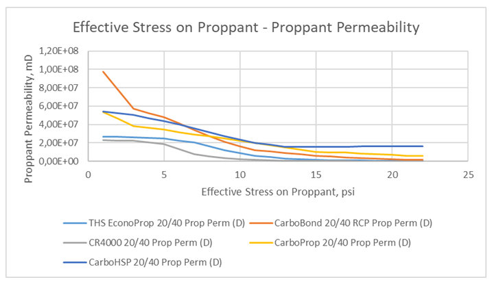
After proppants placed in the fracture aperture, a conductive path is created. This created media in the fracture is based on many factors like proppant resistance and proppant shape. Figure 2 shows the permeability values of different type of proppants under different closure stress values.
![Figure 2: Permeability change of the proppant types under closure stress [9].](/fulltextimages/11886/fig_2.png)
Proppant shape is one of the other important variables that has a great impact on the fracture permeability, conductivity and the proppant pack stability. The expected shape of the proppant is spherical shape with uniform distribution. The sphericity is defined by The International Organization for Standardization (ISO) [10, 11] as “a measure of how close a proppant particle looks like the shape of a sphere”. Moreover, it describes the roundness as “a measure of the relative sharpness of corners or of curvature”. Figure 3 shows how more rounded and spherical proppants create a more conductive path in the fracture than not spherical and not rounded proppant pack.
![Figure 3: Rounded and spherical proppants create a more conductive fracture [12].](/fulltextimages/11886/fig_3.png)
Methodology
There are three different optimization steps are determined to simulate the hydraulic fracture operation on Fracpro software. The first step is deciding the optimum proppant specific gravity, and five different proppants are used in this optimization part. Since the rate is very critical for fracture geometry as second step rate optimization is simulated with the already decided specific gravity from the first step. As the last part of the operation, proppant amount is optimized with the decided specific gravity and rate values from the former steps.
Optimization of Proppant Specific Gravity
There are five different proppant types are taken as example for hydraulic fracturing design. The first type of the proppant is CR4000 20/40 resin coated sand which is a low strength proppant with a specific gravity of 2.53. Second type of the proppant is THS EconoProp 20/40 with a specific gravity of 2.61. Third type of proppant is Carbo Bond 20/40RCP with a specific gravity of 2.72. Forth type proppant is CarboProp 20/40 which is a medium strength ceramic proppant with a specific gravity of 3.28. The fifth type of proppant is CarboHSP 20/40 with a specific gravity of 3.56. For both cases, 100 mesh sand and 40/70 mesh proppants are used. In total, 60 tons of proppant is used in each case. A summary table is given below.
Table 2 depicts that using THS EconoProp 20/40 results in increase in the fracture width, and it has the value of dimensionless conductivity (FcD) which is so close to optimum value. FcD value increases with the use of higher specific gravity proppant. The increase can be described well with the equation (1) which shows the formula of FcD. According to the formula, fracture width is directly proportional with FcD. Additionally, permeability and the fracture length are inversely proportional. Moreover, such critical increase in FcD, brings it close to the optimum value of it. Figure 4 shows optimum FcD value is around 10 and lower or higher than around 10 is actually not desired in terms of hydraulic fracturing design. If you go above 30, you are adding too much effort which is not add more conductivity in return. Figure 5 shows for each proppant, the effective stress on proppant for permeability values which also shows that low specific gravity proppant also has a lower strength value.
| 4000 CR 20/40 (Sg: 2,53) | THS Econo Prop 20/40 (Sg: 2,61) | Carbo Bond 20/40 (Sg: 2,72) | Carbo Prop 20/40 (Sg: 3,28) | CarboHSP 20/40 (Sg: 3,56) | |
|---|---|---|---|---|---|
| 100 mesh | 5 | 5 | 5 | 5 | 5 |
| 40/70 | 25 | 25 | 25 | 25 | 25 |
| XT35 | 30 | 30 | 30 | 30 | 30 |
| Total | 60 | 60 | 60 | 60 | 60 |
| Length (m) | 233,6 | 233,5 | 233,5 | 233,6 | 233,6 |
| Propped Length (m) | 215,6 | 215,5 | 215,4 | 215,3 | 215,2 |
| Height (m) | 84,6 | 84,6 | 84,6 | 84,7 | 84,6 |
| Propped Height (m) | 78 | 78 | 78 | 78 | 78 |
| Width (mm) | 0,115 | 0,119 | 0,117 | 0,108 | 0,102 |
| FcD | 3,931 | 9,347 | 15,067 | 18,68 | 18,446 |
Table 2: Created Hydraulic Fracture Properties of 4000CR 20/40 and CarboProp 20/40.
$$ C _ {f D} = \frac {k _ {f} w}{k X _ {f}} $$
(1)
![Figure 4: Equivalent wellbore radius as a function of dimensionless fracture conductivity and fracture length [9].](/fulltextimages/11886/fig_4.png)
Optimization of Rate
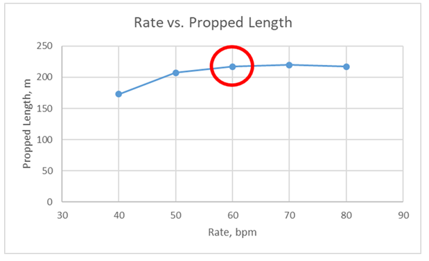
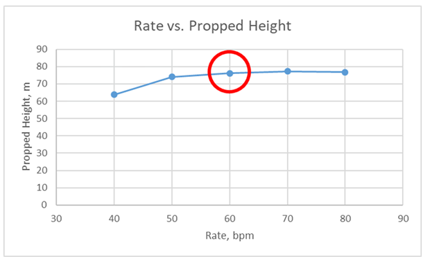
Pumping rate is an essential parameter of hydraulic fracturing treatments, because it directly affects the hydraulic horsepower that is used in the hydraulic fracturing operation. Therefore, pumping slick water, proppant and any other chemicals are under direct impact of the rate parameter. There is a simulation is conducted to see the effect of pumping rate on the fracture parameters. Figures 6 & 7 show the changes in both propped length and propped height. Therefore, with the increase of rate causes the geometry of fracture increase in both cases. In these two figures the optimum values for 60 bpm rate look sufficient, and they are circled with red.
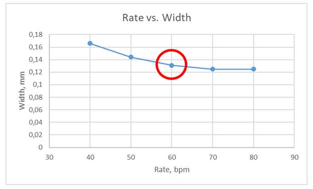
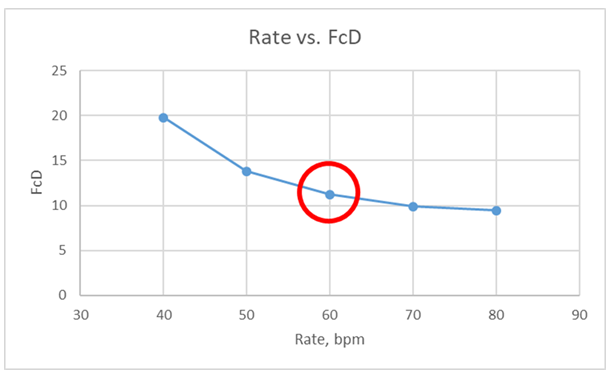
On the other hand, on the fracture width and FcD values there are respectively proportional increase and decrease are detected. In figure 8, rate 60 bpm looks very promising in the light of the length and height graphs. Moreover, figure 9 shows that FcD gives an optimum value which is close to 10, at 60 bpm.
Optimization of Proppant Amount
Proppant amount optimization is a vital point of optimization [13] of hydraulic fracturing because the operation price can be very high or low according the success of it. To decide the proppant amount in this simulation study; 40, 60, 80, 100, 120 ton of proppant amounts are used for comparing the results. Figure 10 shows that propped length generally increases with the increasing proppant amount, but it is not directly proportional with the proppant amount, and when proppant amount increases from 80 to 100 the length slightly increases or stays stable. Figure 11 shows propped height behavior for given proppant amounts. When proppant amount increases to 100, propped height slightly increases.
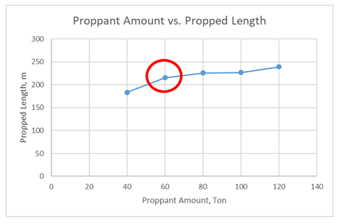
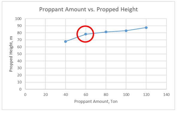
Figure 12 shows fracture width response to increase of proppant amount. Generally, with the increase of the proppant amount the fracture width increases. Specifically, the increase in the proppant amount from 80 to 100 results with an increasement in the fracture width.
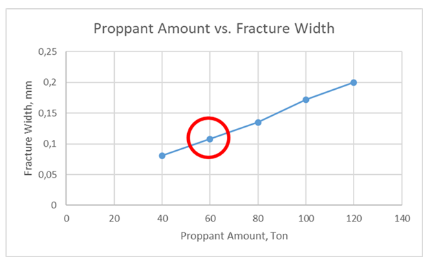
Figure 13 shows FcD responses for different number of proppants, and it generally shows a steady increasing line as a response of the proppant amount change. When the proppant amount reaches a certain point, in this case its 100 tons, FcD gets the highest value. If you use more proppant above 100 tons, this will not help the increase in FcD, so production.
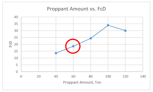
In the light of the fracture length, fracture heigth, fracture width and FcD graphs 100 tonnes of proppant use looks reasonable for the sake of optimization.
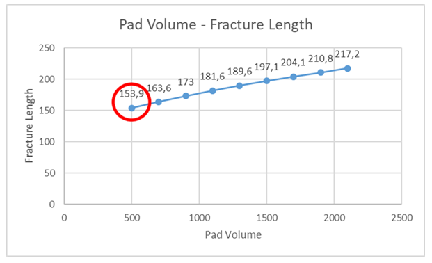
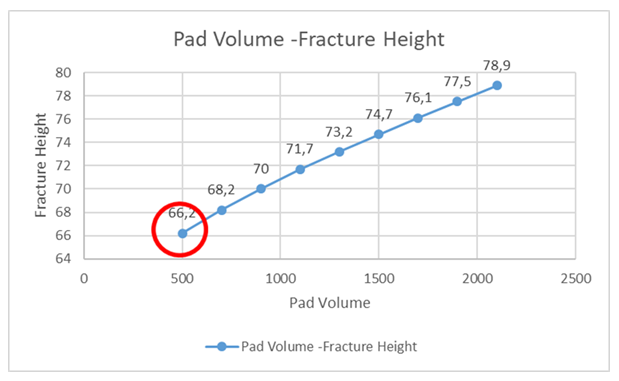
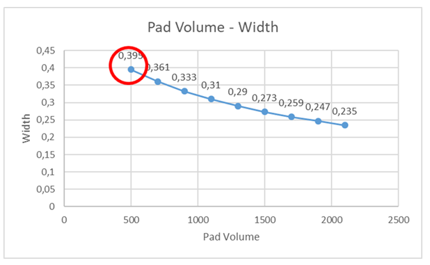
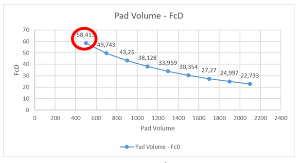
Pad Volume Optimization
By attending different pad volume values for each of the treatment, a more suitable value tried to obtain. In this study from 500 bbls to 2100 bbls pads are pumped, and around 500 bbls pad volume the optimum point is detected. While 500 bbls giving the highest FcD, in terms of the price it will costs the minimum when we also consider other expenses like sweep fluid in the treatment (Figures 14-17).
Result
Hydraulic fracturing optimization should be done with consideration of many factors. The ones taken account in this optimization study are specific gravity, rate, proppant amount and pad volume optimization. To obtain these most important features for a hydraulic fracturing operation, the parameters and FracPro software runs were conducted. The specific gravity simulations show higher the specific gravity higher a proppant has the strength and FcD. Therefore, in FracPro runs, the FcD value was in a trend of increase with the increase of the specific gravity. The reason FcD increases is because the strength of the proppant increases with the specific gravity. Thus, proppant crushes less than the weak ones. For this step, THS EconoProp 20/40 proppant with a specific gravity of 2.61 was decided to be utilized. The rate study gives results as the increase in the rate results with the increase in the fracture geometries. Therefore, propped length and height values increase. Specifically, at 60bpm level the fracture length and height look the optimum.
Proppant amount is one of the vital steps of the hydraulic fracturing optimization, and in this study different proppant amounts are taken into consideration, namely, 40, 60, 80, 100, 120 tons proppant were pumped. The results depicted that 60 tons of proppant use gives the optimum proppant amount to pump. Pad volume was decided to be taken as 500 bbl. considering the operation efficiency at optimum. Even though with low amount of pad volume the fracture width increases, with low permeability formation, it will not impact our production directly positively.
References
-
Alagoz E, Wang H, Russell RT, Sharma MM (2020) New Experimental Methods to Study Proppant Embedment in Shales. Rock Mechanics and Rock Engineering 55: 2571-2580.
-
Alagoz E, Sharma MM (2021). Investigating Shale-Fluid Interactions and Its Effect on Proppant Embedment Using NMR techniques. US Rock Mechanics/Geomechanics Symposium, pp: 2021-1129.
-
Dundar EC, Mengen AE, Mironov VS, Khlopkov A, Alagoz E (2023) An analytical study of hydraulic fracturing optimization for tight shale formation. 21th International Petroleum and Natural Gas Congress and Exhibition of Turkiye.
-
Alagoz E, Yaradilmis Y (2023) Evaluation of Resin Coated Proppants A New Custom Method. International Journal of Earth Sciences Knowledge and Applications 5(2): 237-243.
-
Suponik T, Labus K, Morga R (2023) Assessment of the suitability of coke material for Proppants in the hydraulic fracturing of Coals. Materials 16(11): 4083.
-
Wilcox C, Fuss T, Shi J, Thompson M, Herskovits R (2015) Proppant Selection Criteria and Their Influence on Performance of North Dakota Oil-Rich Shale Wells. Unconventional Resources Technology Conference.
-
Greff K, Greenbauer S, Huebinger K, Goldfaden B (2014) The Long Term Economic Value of Curable Resin Coated Proppant Tail in to Prevent Flowback and Reduce Workover Cost. Unconventional Resources Technology Conference.
-
Graham JW, Muecke TW, Cooke CE, Everett C (1975) Method for Treating Subterranean Formations. US Patent.
-
Economides MJ, Nolte KG (2000) Reservoir stimulation. Wiley, pp: 856.
-
European Committee for Standardization (2011) TS EN ISO 13503-2: Petroleum and natural gas industries - Completion fluids and materials Part 2 Measurement of properties. CEN.
-
International Organization for Standardization (2006) ISO 13503-2: Petroleum and natural gas industries Completion fluids and materials Part 2 Measurement of properties. ISO.
-
Nash S (2018) Proppant Technology Advances and Reservoir Performance. pp: 3-27.
-
Alagoz E, Guo Y, Li L (2023) Optimization of Fracture Treatment Design in a Vertical Well. Petroleum and Petrochemical Engineering Journal 7(4): 1-16.
- Plant Diversity, Regeneration Dynamics, and Socio-Ecological Impacts at the Forest-Savanna Transition Zone, Cameroon
- Bird Community, Feeding Guilds and Habitat Associations Along the Proposed River Dibombe Hydropower and Transmission Line Project in Nkam and Moungo Divisions, Cameroon
- Plant Diversity and Carbon Storage Potential Across Different Land Use Types in Infrastructure Development Landscapes in Cameroon: Implications for no Net Loss of Biodiversity
- Optimization and Modelling for the Remediation of Brilliant Green Dye and Ni2+ ions from Water Using Advanced gC3N4/PVA@ Alginate Bio-Polymeric Hydrogel Beads
- The Negative Implications of Using Cell Phones on Human Health and Environment
- A Comprehensive Survey of Population Ecology in Insects