Micro-Modulations of Titanium Oxide Coatings Formed Using a Femtosecond Laser
Highly useful microstructures are required in order to enhance the properties of titanium oxide (TiO2) coatings, so as to substantially increase the surface and underlayer surface areas. Along with coating deposition techniques, femtosecond laser irradiation has high capability to control micro-modulations consisting of mesopores and microspheres, with no unexpected damage due to thermal expansion. In this study, phase contrast microscopy (PCM) is employed in conjunction with differential-emphasis and contrast-enhancement image-processing techniques. This approach is confirmed to allow precise identification of the refractive index modulation generated in the TiO2 coatings. The effects of the laser output per pulse (5-10 μJ) and the pulse number (1-1000) on the TiO2-coating ablation craters formed by the femtosecond laser irradiation are also investigated. The double ridges are composed of inner and outer crater edges, the clarity R of which is characterized by the difference between the inner and outer diameters. This value is distinct and increases with increasing laser output for single-pulse irradiation. For high-pulse-number irradiation, the superposition of the collapsed circles created by multiple fluctuating pulses decreases R. Differential-emphasis PCM images, which emphasize the difference in image intensity between adjacent image pixels, facilitate identification of surface periodic structures in ablation craters formed by five pulses or less. Further, contrast-enhanced PCM images are found to reveal microspheres mechanically propelled by the laser beam from the interiors to the peripheries of the ablation craters. The micro-modulations in the TiO2 coatings formed by the femtosecond laser irradiation and revealed by the PCM images are expected to modify the nano-adsorbency of this material for more effective use in water treatments, by increasing the coating surface areas.
Introduction
Titanium oxide (TiO2) can be used to create functional coatings, which have applications such as photocatalysis and photoluminescence [1, 2]. Further, the microspheres and mesopores formed in TiO2 coatings, the spatial profiles of which are controlled by the coating deposition conditions, are expected to enhance the catalysis and nano-adsorbency properties of TiO2 [3, 4]. Femtosecond laser micromachining can form highly useful microstructures in the coating surface, underlayers, and inner layers, without destruction due to thermal expansion [5]. The characteristics of the TiO2 coatings are modified as a result of the changes in the electron orbits and band structures of the microstructures formed by the femtosecond laser irradiation. The possibility of controlling the electrical properties of the TiO2 coatings is expected, because femtosecond laser micromachining produces microcrystalline structures [6]. Further, an intensity region bounded by lower and upper thresholds and suitable for the enhancement of the properties of TiO2 coatings through femtosecond laser irradiation has previously been revealed. Changes in the surface morphology and electrical resistance of TiO2 coatings have been induced above and below certain laser intensities, respectively [7]. In addition, the surface periodic structures (ripples) that appear on crystal and metal surfaces self-formed under the influence of femtosecond lasers have been applied in scientific and industrial fields [8, 9, 10]. In order to improve the characteristics of TiO2 coatings, highly reproducible conditions should be surveyed over parameters such as the coating thickness, laser output, number of pulses, focal-point positions, and angles of incidence and polarization [11]. The aim of this study is to achieve increases in the surface areas of TiO2 coatings, which are necessary for applications such as water treatment, using femtosecond laser micromachining. An additional aim is to present new observation and image processing techniques that can be used with conventional scanning electron microscopes (SEMs) to identify micro- modulations in the TiO2 coatings.
Materials and Methods
Samples were prepared by depositing TiO2 coatings on fused glass and ST-cut single-crystal quartz substrates using the ion-beam sputtering technique. A target disk of Ti metal was sputtered with an Ar ion beam, and the oxide coatings were formed reactively by the supply of O2 gas to the substrate via a nozzle. The TiO2 coating deposition rate was typically 0.5 nm/min, and the substrate temperature during deposition increased by several degrees. The thickness of the TiO2 coatings on fused glass was 100 nm.
A commercial Ti:sapphire laser was used as the femtosecond laser system for irradiating the TiO2 coating (Hurricane, Spectra Physics). A regenerative amplifier was used to obtain femtosecond laser pulses. The final output energy was 0.8 mJ per pulse with a repetition rate of 1 kHz. The fundamental wavelength was 800 nm and the laser bandwidth was 10 nm. The full width at half maximum of the laser pulse width was 100 fs. The beam diameter before focusing was 6.0 mm. The laser pulse energy was controlled by an energy attenuator composed of a thin film polarizer and a half-wave plate. The output per pulse ranged from 5 to 10 µJ. The laser pulse was focused vertically on the TiO2 coating by a fused silica plano-convex lens with 100-mm focal length, where an electric field was applied parallel to the coating. The beam diameter after focusing on the TiO2 coating was estimated to be 20 µm. PCM (ODEO-2222, Iponacology) and scanning electron microscopy (SEM) (VE-8800, Keyence) were used to visualize the micro-modulation formed by the laser irradiation on the TiO2 coating. The PCM illumination utilized a green light-emitting diode (LED) and the images were processed numerically. The SEM acceleration voltage was 1 kV.
Micro-Modulation on TiO2 Coatings
Electron Microscopy and Phase-Contrast Microscopy
SEM and PCM images of an ablation crater formed at the focus point of 300 femtosecond laser pulses with 5-μJ output are shown in Figure 1(a). An SEM image of the TiO2 coating before laser irradiation is shown in Figure 1(b). Four positions for magnification: (c) top, (d) left, (e) right, and (f) bottom are indicated in the PCM image in Figure 1(b). The image intensities (pixel values) in the PCM images were numerically processed. In the four sets of magnified images shown in Figures 1(c-f), micro- modulations identified by the [α] SEM, [β] PCM, and [γ] relief contours are compared. The SEM visualized the granular structure of the surface layer and reduction of the surface layer inside the ablation crater, while the PCM was expected to visualize the refractive index modulation generated in the surface and underlayers. The relief contour maps constructed from the PCM images were effective for identifying the micro-modulation on the coating.
![Figure 1: Comparison of SEM and PCM images of ablation crater formed with 6-µJ laser output for 300 pulses. (a) Complete image of ablation crater. (b) SEM showing TiO2 coating before laser irradiation and PCM indicating four positions for magnification. In the magnified images of the (c) top, (d) left, (e) right, and (f) bottom, the micro- modulations are compared with [α] SEM and [β] PCM. [γ] Relief contour map constructed from PCM image.](/fulltextimages/515/fig_1.jpeg)
Figure 1: Comparison of SEM and PCM images of ablation crater formed with 6-µJ laser output for 300 pulses. (a) Complete image of ablation crater. (b) SEM showing TiO2 coating before laser irradiation and PCM indicating four positions for magnification. In the magnified images of the (c) top, (d) left, (e) right, and (f) bottom, the micro- modulations are compared with [α] SEM and [β] PCM. [γ] Relief contour map constructed from PCM image.
Double Ridge Formed by Low-Pulse-Number Irradiation
Figure 2 shows the PCM images of ablation craters formed by femtosecond laser pulses of 6–10 µJ per pulse, for (a) 1, (b) 3, and (c) 5 pulses, where the green LED generated a green background. The shapes formed by a single pulse were identified as collapsed circles, i.e., ellipses, especially for the 9- and 10-µJ laser outputs. Line- or dot-shaped irregularities on the TiO2 coatings were sometimes formed during the coating deposition. When the line-shaped deposition irregularities crossed the ablation craters, they remained there for single-pulse irradiation with 6-, 8-, and 9-µJ outputs (Figure 2(a)). The line-shaped irregularities were gradually removed from inside the craters by using a greater number of pulses. A greater number of pulses are more effective for removing the line-shaped irregularities than a greater laser power output. The line-shaped irregularities remained partially inside the ablation craters for three 8-µJ pulses and three 9-µJ pulses (Figure 2(b)), and were completely removed by five 10-µJ pulses (Figure 2(c)).
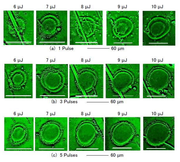
Figure 2: Ablation craters on TiO2 coating formed by (a) one, (b) three, and (c) five pulses with 6–9-µJ laser outputs. The single pulse shapes deviated from a true circle (a). Although line-shaped deposition irregularities are recognizable, double ridge formation can be identified. The double ridges are more distinct for low-pulse irradiations. The line-shaped irregularities that cross the ablation craters are removed by more than three pulses (c).
Double ridges, characterized by the inner and outer diameters, are identifiable on the circumferences of the ablation craters. Because each double ridge is constructed from inner and outer ellipses, the major and minor diameters are determined along the major and minor axes, respectively. Thus, the major, minor, and averaged inner diameters: ra, rb, and <r>, respectively, and the major, minor, and averaged outer diameters: Ra, Rb, and <R>, respectively, can be defined, where <r> = (ra + rb)/2 and <R> = (Ra + Rb)/2. The clarity of a double ridge is characterized by the difference R = <R>−< r> between the averaged outer and inner diameters. Figure 3 shows the relationship between the laser output (abscissa) and R (ordinate), where R increases with increasing laser output for single-pulse irradiation. The decreases in ΔR with increasing laser output for multiple laser pulse irradiations are related to the superposition of the fluctuating multiple pulses as discussed in the next section.

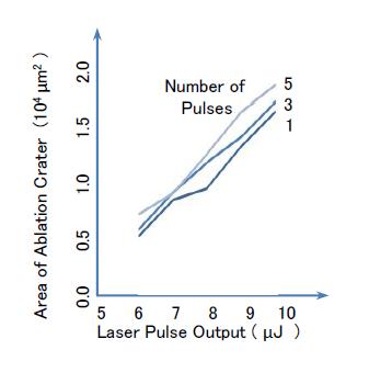
The area formula for an ellipse is used to determine the area S of the ablation crater as S = πRaRb. Figure 4 shows the relationship between the laser output (P, abscissa) for one, three, and five pulses, and the areas of the ablation craters (S, ordinate). The linear relationship between S and P was estimated to be S = α(P – P0), (1) Where α and P0 are proportional coefficients and functions of the pulse number and work function, respectively. Figure 4 demonstrates that the remaining power obtained by subtracting the work function from the irradiated laser output is used for the formation of the ablation crater.
Superposition of Fluctuating Multiple Pulses
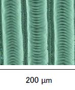
Figure 5 shows a PCM image of three stripes on fused silica that were formed by successive shifts of the pulse center by 10 µm between each 10-µJ single pulse. The variations of the crater edges revealed the fluctuations of both the center and shape of each single pulse. The single pulse shapes deviated from a true circle, as shown in Figure 2(a). Therefore, the superposition of the centers and shapes of the fluctuating multiple pulses deteriorates R, as shown in Figures 2 and 3, where ΔR decreases with the increase of the pulse number from three to five pulses.
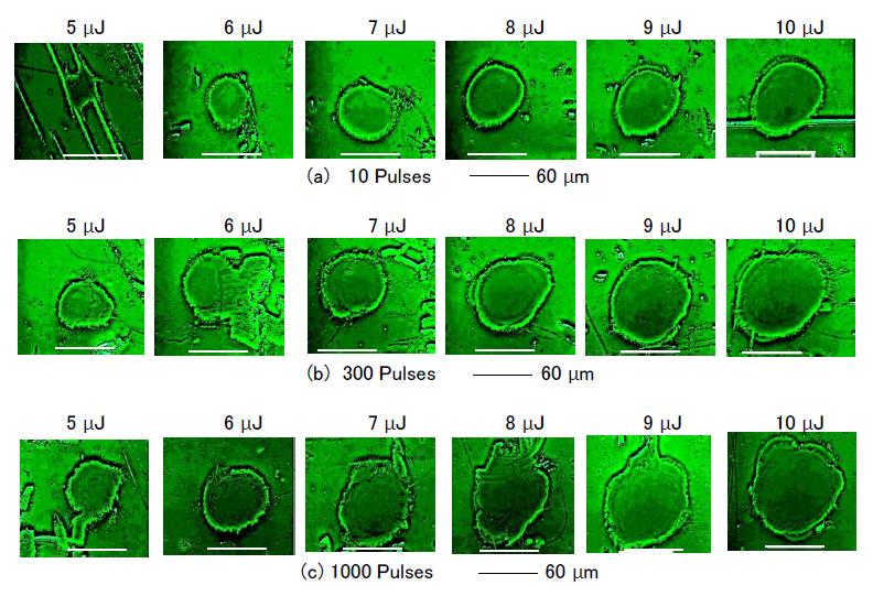
Figure 6 shows PCM images of ablation craters formed with 5–10-µJ outputs for different numbers of pulses ((a) 10, (b) 300, and (c) 1,000).
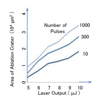
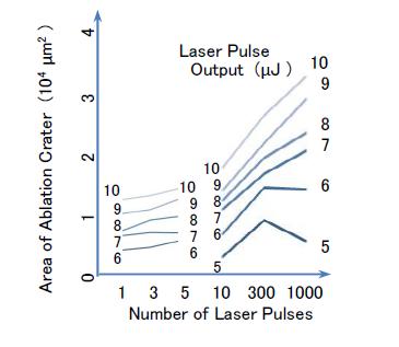
ΔR is more distinct for low-pulse irradiations, because of the superposition of the centers and shapes of the fluctuating multiple pulses, as shown by a comparison between Figures 2 and 6. However, double ridges can be identified on several partial segments; for example, the ablation craters formed by 9- and 10-µJ outputs for 10, 300, and 1,000 pulses, and with an 8-µJ output for 300 pulses. Line-shaped deposition irregularities were found outside the ablation craters for 10 pulses with 5- and 10- µJ outputs (Figure 6(a)), and were completely removed by 300 pulses with 10-µJ output (Figure 6(b)). Figure 7 shows the relationship between the laser output (abscissa) for 10, 300, and 1,000 pulses and the areas of the ablation craters (ordinate). Because the linear relation between the area and laser output, as shown in Equation (1), is also expected in Figure 7, the remaining power obtained by subtracting the work function from the irradiated laser output is expected to be used for ablation crater formation for pulse numbers from 1 to 1,000. Figure 8 shows the relationship between the number of pulses and the ablation crater area. Despite the concise linear dependence of the ablation crater area on the laser output, the dependence of the area on the number of laser pulses is comparatively weak. However, the remaining power obtained by subtracting the work function is expected to be used for the crater formation, as shown in Equation (1), because the energy required to form one ablation crater is a product of the laser output and pulse number.
No ablation craters were formed for five or less pulses, as shown in Figure 2, because the clarity of the ablation craters formed with a 5-µJ output was poor. The ablation craters formed with a 5-µJ output for 10 or more pulses exhibited comparatively lower diameters, except for those formed by 300 pulses with a 5-µJ output, as shown in Figure 6(b).
Identification of Surface Periodic Structures and Microspheres
Surface periodic structures are often created by the interference of incident and scattered light within the coatings [8]. The surface period created by normal laser incidence is given by λ/n, where λ and n are the laser wave length and the refractive index of the laser ablation plasma on the surface. Figure 9 shows the surface periodic structures formed by laser irradiation with (a) three 6-µJ pulses inside the ablation crater, and (b) five 8- µJ pulses on the lower segment of the double ridge. The PCM images are shown in column [α]. The differential- emphasis images constructed from the PCM images emphasize the difference in image intensity between adjacent image pixels and are shown in columns [β,γ]. Intensity and relief contour maps constructed numerically from the PCM images are shown in columns [δ] and [ε], respectively, where the brightness agrees with the image intensity. The refractive index modulations can be identified by considering the contrast-enhanced and differential-emphasis images, and the intensity and relief contour maps. The differential-emphasis images and relief contour maps are suitable for identifying the surface periodic structures shown in Figure 9(a), while the differential-emphasis images and intensity contour maps are suitable for identifying the surface periodic structures shown in Figure 9(b). Thus, the differential-emphasis technique is expected to be most suitable for the identification of the surface periodic structures in both Figures 9(a) and (b), and either the intensity or the relief contour map is suitable for additional identification. The surface periods are determined to be 2.3 and 2.9 µm in Figures 9(a) and (b), respectively, Note that the distance corresponding to six surface periods is shown in Figure 9(b). Because the surface periods are greater than the laser wave length, the refractive index of the ablation plasma is less than 1.
![Figure 9: Surface periodic structures found in ablation crater interior formed by laser irradiation with (a) three 6-µJ pulses, and on lower segment of laser-irradiation-induced ablation crater formed with (b) five 8-µJ pulses. [α] PCM image of ablation crater. [β] Differential-emphasis image constructed from contrast-enhanced PCM image. [γ] Magnified image of surface periodic structure region. [δ] Intensity contour map and [ε] relief contour map constructed from contrast-enhanced PCM. The surface periods are 2.3 and 2.9 µm in (a) and (b), respectively.](/fulltextimages/515/fig_9.jpeg)
Figure 9: Surface periodic structures found in ablation crater interior formed by laser irradiation with (a) three 6-µJ pulses, and on lower segment of laser-irradiation-induced ablation crater formed with (b) five 8-µJ pulses. [α] PCM image of ablation crater. [β] Differential-emphasis image constructed from contrast-enhanced PCM image. [γ] Magnified image of surface periodic structure region. [δ] Intensity contour map and [ε] relief contour map constructed from contrast-enhanced PCM. The surface periods are 2.3 and 2.9 µm in (a) and (b), respectively.
Microspheres in the periphery of the ablation craters can be observed in several positions in Figures. 2 and 6. That is, microspheres that have been propelled mechanically by the laser beam from the inside to the periphery of the ablation crater can be identified. Figure 10 shows microspheres on the lower segments of the ablation craters formed by five pulses of (a) 6 µJ and (b) 7 µJ, and on the upper segments of the ablation craters formed by (c) three pulses of 8 µJ and by (d) 300 pulses of 10 µJ. The differential-emphasis images constructed from the contrast-enhanced PCM images are shown in column [α]. The intensity and relief contour maps constructed from the contrast-enhanced PCM images are shown in columns [β] and [γ], respectively, where the brightness indicates the image intensity. While the differential- emphasis images are suitable for identifying the positions of microspheres in a manner similar to the identification of the surface periodic structures indicated in Figure 9, the intensity contour maps are more suitable for identifying the microspheres propelled from the insides to the peripheries of the ablation craters, where the microspheres are indicated by white arrows in columns [β]. The relief contour map in Figure 10 was not suitable for identifying the microspheres, in contrast to its usefulness in identifying the surface periodic structures shown in Figure 9.
![Figure 10: Microspheres found on lower segments of ablation craters formed by laser irradiation with (a) five 6-µJ pulses and (b) five 7-µJ pulses, and on the upper segments of ablation craters formed with (c) three 8-µJ pulses and (d) 300 pulses of 10 µJ. [α] Differential-emphasis image constructed from contrast-enhanced PCM. [β] Intensity contour maps and [γ] relief contour maps constructed from contrast-enhanced PCM, where microspheres propelled from the interior to the periphery of the ablation crater are identified in the intensity contour map and indicated by white arrows[β].](/fulltextimages/515/fig_10.jpeg)
Figure 10: Microspheres found on lower segments of ablation craters formed by laser irradiation with (a) five 6-µJ pulses and (b) five 7-µJ pulses, and on the upper segments of ablation craters formed with (c) three 8-µJ pulses and (d) 300 pulses of 10 µJ. [α] Differential-emphasis image constructed from contrast-enhanced PCM. [β] Intensity contour maps and [γ] relief contour maps constructed from contrast-enhanced PCM, where microspheres propelled from the interior to the periphery of the ablation crater are identified in the intensity contour map and indicated by white arrows[β].
Discussion
In this study, we found that PCM is useful for identifying micro-modulation on TiO2 coatings, and developed the image processing techniques required for numerically constructing intensity and relief contour maps of PCM images. A comparison between differential interference contrast microscopy and PCM images, using differential-emphasis and contrast-enhancement image- processing techniques, will be necessary for more precise identification of the micro-modulations in the surface and inner layers. It was found that the deposition irregularities are gradually removed from inside the ablation craters using a greater number of pulses. Further, structural irregularities such as double ridges, surface periodic structures, and microspheres are formed using a lower number of pulses. Thus, it is proposed that a lower pulse number for the femtosecond laser is preferable. Changes in the angles of incidence and polarization are expected to facilitate precise control of the micro-modulation of the TiO2 coatings, because the experiments conducted in this study adopted normal incidence only.
Conclusions
Microstructures required to enhance the properties of TiO2 coatings can be formed via femtosecond laser irradiation, without destruction due to thermal expansion. Femtosecond laser micromachining has the capability to control the micro-modulations so as to substantially increase the TiO2-coating surface areas. The micro-modulations generated in the TiO2 coatings should be detected precisely in order to reveal the resultant microstructures in the surface and underlayers. The advantage of using a phase contrast microscope (PCM) over a scanning electron microscope (SEM) for such detection is the resultant visualization of the refractive index modulation generated in the coating surface and underlayers. In this study, PCM was confirmed to allow identification of ablation craters with double ridges, surface periodic structures, and microspheres, which were formed by femtosecond laser irradiation of the TiO2 coatings. Note that the PCM was assisted by appropriate image-processing techniques such as contrast enhancement and differential emphasis.
The effects of the laser output per pulse and the pulse number on the TiO2-coating ablation craters, which were formed at the focal points of the femtosecond laser pulses, were also investigated. For this part of the study, the laser output per pulse ranged from 5 to 10 μJ and the pulse number ranged from 1 to 1000. Owing to the linear relationship between the ablation crater area and the laser output, the remaining power obtained by subtracting the work function from the irradiated laser output was expected to be used for the ablation crater formation. The structures of the double ridges composed of inner and outer crater edges were distinct for pulse numbers less than or equal to 5. ΔR, which was characterized by the difference between the inner and outer crater edge diameters, was distinct and increased with increasing laser output for single-pulse irradiation. In general, R decreased with increasing pulse number owing to the superposition of the centers and shapes of the multiple fluctuating laser pulses, which had the form of collapsed circles. Double ridges could be identified on several partial segments of the ablation craters for pulse numbers greater than or equal to 10. Based on the results of this study, the differential- emphasis technique is expected to be most suitable for the identification of surface periodic structures in ablation craters formed by five or less pulses, and either an intensity or a relief contour map is suitable for additional identification. Further, coating irregularities formed before laser irradiation can be gradually removed through application of a greater number of pulses. The microspheres that are propelled mechanically from the interiors to the peripheries of the ablation craters can be identified in contrast-enhanced PCM images. The main limitation of this study is that the micro- modulations in the TiO2 coatings formed by the femtosecond laser were not supported by the adsorption, catalysis, and electric-current surface characteristics. Future related research questions include the following: 1) Laser incidence: The effects of the incident angle (oblique incidence), the polarization surface angle, and the focal point deviation from the surface can be investigated as functions of the laser intensity and pulse number, along with the coating thickness. 2) Surface identification: The use of SEM, PCM, and differential interference contrast microscopy, which are assisted by image processing techniques such as contrast emphasis, differential emphasis, and intensity and shadow relief mapping, will reveal the precise modulations in the TiO2 coatings. 3) Physical chemistry: The coating depositions and micro-modulations can be evaluated based on the adsorption of nitrogen molecules and metal atoms, and by examining the surface electric resistance. By performing these experiments and measurements comprehensively, it is expected that the micro-modulations in the TiO2coatings controlled using femtosecond laser irradiation can be fully utilized for more effective application (e.g., in waste water treatment), having high surface and underlayer surface areas and high reproducibility.
Acknowledgement
This work was partially supported by the joint research project of the Institute of Laser Engineering, Osaka University. The authors T.O. and Y.I. are grateful to the late Dr. C. Yamanaka, Professor Emeritus of Osaka University.
References
-
Ohko Y, Tatsuma T, Fuji T, Naoi K, Niwa C, et al. (2003) Multicolour photochromism of TiO2 films loaded with silver nanoparticles. Nat Mater 2: 29-31.
-
Preclíková J, Galář P, Trojánek F, Rezek B, Nĕmcová Y, et al. (2011) Photoluminescence of nanocrystalline titanium dioxide films loaded with silver nanoparticles. J Appl Phys 109: 083528.
-
Li X, Sun Y, Zhang Y, Cao M (2015) Facile preparation of mesoporous titanium nitride microspheres as novel adsorbent for trace Cd2+ removal from aqueous solution. J Phys and Chem Solids 81: 20-26.
-
Shahat A, Awual R, Khaleque A, Alam Z, Naushad Mu, et al. (2015) Large-pre diameter nano-adsorbent and its application for rapid lead(II) detection and removal from aqueous media. Chem Eng J 273: 286- 295.
-
Izawa Y, Tokita S, Fujita M, Nakai M Norimatsu T, Izawa Y (2009) Ultrathin amorphization of single- crystal silicon by ultraviolet femtosecond laser pulse irradiation. J Appl Phys 105: 064909.
-
Ichikawa Y, Setune K, Kawashima S, Kugimiya K (2001) Microcrystal structures in titanium oxide films produced by pulsed UV-laser irradiation. Jpn J Appl Phys 40: L1054-L1057.
-
Tsukamoto M, Abe N, Soga Y, Yoshida M, Nakano H, et al. (2008) Control of electrical resistance of TiO2 films by short-pulse laser irradiation. Appl Phys A 93: 193- 196.
-
Sakabe S, Hashida M, Tokita S, Namba S, Okamuro K (2009) Mechanism for self-formation of periodic grating structures on a metal surface by a femtosecond laser pulse. Phys Rev B 79: 033409.
-
Matsumoto S, Yane A, Nakashima S, Hashida M, Fujita M, et al. (2007) A rapid flow mixer with 11-μs mixing time microfabricated by a pulsed-laser ablation technique: Observation of a barrier-limited collapse in cytochrome c folding. J Am Chem Soc 129(13): 3840-3841.
-
Tsukamoto M, Kawa T, Shinonaga T, Chen P, Nagai A, et al. (2016) Cell spreading on titanium periodic nanostructures with periods of 200, 300 and 600 nm produced by femtosecond laser irradiation. Appl Phys A 122:120.
-
Osuga T, Fujita M, Ichikawa Y (2013) Microstructure formation of titanium oxide (TiO2) coatings by femtosecond laser irradiation. J Ceram Soc Jpn 121(9): 813-815.
- Solution-Processed Chiral Perovskites for Biomedical Applications
- Nanotechnology in Health Chemistry and Medicine: Current Challenges and Future Directions
- Human Exposure to Micro- and Nanoplastics: Pathways, Toxicity, and Intervention Strategies
- Exosome Nanomedicine for Cancer Therapy
- Micro and Nanoplastics–Plastisphere, Biotoxicity, Impact on Human Health, and Mitigation Strategies
- Process Validation of Cefixime Powder for Suspension Dosage Form, 50 mL