Precise Iris Positioning in Ocular Prosthesis Using an Eyewear
Positioning the iris to the ideal symmetrical position is a critical step in the fabrication of an ocular prosthesis. A correctly placed iris lends a natural and aesthetic appearance to the ocular prosthesis whereas any asymmetry in this position leads to a squinted eye look.
Introduction
The loss or absence of an eye may be the result of congenital defects, irreparable trauma, tumor, sympathetic opthalmia, etc. Surgical intervention for these ocular lesions often includes the following approaches: evisceration, enucleation or exenteration [1]. The disfigurement caused after an eye loss causes significant physical and psychological disturbance to the patient. Psychological distress can be reduced by timely replacement with suitable ocular prosthesis (stock or custom) [2] Prosthetic replacement of lost eye presents with many challenges one of which being accurate positioning of iris [3]. Any asymmetry in positioning causes a squinted eye appearance which leads to unaesthetic results. Various techniques have been described in literature regarding the proper positioning of the iris. These include use of pupilometer [4], ocular locator [5], facial landmarks, visual assessment [6], and graph grid [7]. The present article describes a simple technique to accurately locate the symmetric position of iris disk assembly while fabricating the prosthesis.
a. A 46 years old male patient was referred to the department of Prosthodontics with a defect in the right eye. Case history revealed that patient lost his right eye two years back due to traumatic accident.
b. On examination, the defect had a properly healed mucosa and sufficient area that would retain the prosthesis. Hence it was decided to fabricate the custom ocular prosthesis.
c. Conventional steps of fabrication were followed till the try in of wax pattern. The wax pattern onto which the iris had to be placed was well finished to have a pleasing contour with the eyelid.
d. A suitable stock eye having an iris that matches the size and shade of contra lateral eye was selected. The stock eye was trimmed to eliminate the scleral portion and the iris was obtained.
e. A used spectacle frame devoid of glasses was selected for the patient.
f. The transparent graph grid was then fabricated by photocopying paper graph grid on a transparent projector sheet.
g. Transparent graph grid was cut into two equal cutouts such that they fit precisely into the spectacle frame and the size and markings were equal on both the cutouts. (Horizontal and vertical lines on both transparent grid cutouts were coincident to each other.) h. The cutout grids were then attached to the eyewear frame using cynoacrylate glue.
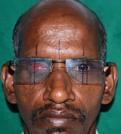
i. The patient was asked to look forward and hold the position of the left eye at a normal conversational gaze after wearing the eyewear.
j. The medial and lateral borders of iris of the left eye were marked on the grid. A vertical line was marked through the centre of pupil on the grid using an indelible ink marker. The outline of the iris was then traced. The vertical line was then extended onto the skin of forehead of the patient. A similar line was drawn on the contra lateral side at the exact position after counting the vertical and horizontal lines on the grid.
k. A horizontal line was drawn on the grid through the centre of pupil extending to the contra lateral side grid and on the skin laterally. These horizontal extensions also provide reference points to suitably align the eyewear frame to a constant position repeatedly (Figure 1).
l. The eyewear was removed and the vertical and horizontal lines were extended to meet on the wax sclera blank which gave the exact position of centre of the iris (Figure 2).
m. The Iris disk was positioned in the wax scleral blank and confirmed by wearing the eyewear again such that the position of the iris corresponded to the markings made on the grid.
n. The eyewear was removed and position of the iris was checked for symmetry with patient engaged in conversational gaze (Figure 3A).
o. The prosthesis was flasked, polymerized, finished, polished, stained and delivered to the patient. (Figure 3B).
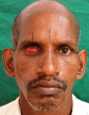
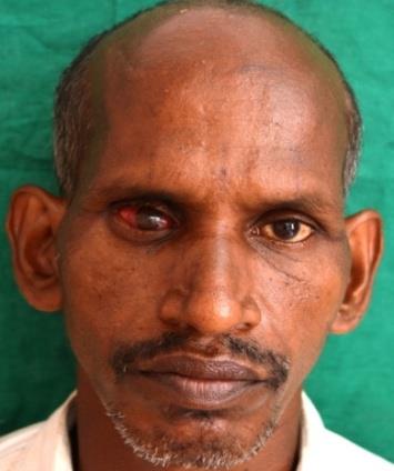
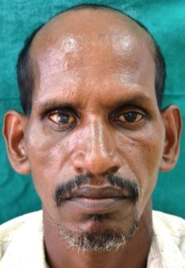
a b Figure 3: a. Iris positioning confirmed on the wax blank; b.
Prosthesis delivered to the patient.
Discussion
An ocular prosthesis should mimic the natural eye as far as possible, especially the iris. Care has to be taken to obtain the correct interpupillary distance and positioning with respect to the natural eye. Mc Arthur described the technique of using ocular locator for proper positioning of an artificial eye in orbital prosthesis. He also advocated relating the pupil of prosthetic eye to existing natural pupil by facial measurements [5]. Roberts described the use of Pupilometer [4]. Benson suggested the use of visual assessment as a method of choice [6]. The method described here is a simple procedure and is a modification of previously described methods for positioning of the iris. Reference points used here are both vertical and horizontal lines marked on the skin extending through the centre of pupil and hence act as a better guide in comparison to inner can thus of eye alone as used previously in literature [3].
Advantages of the present technique are
a. It is a simplified technique requiring less chair side time and armamentarium. b. The use of a transparent graph grid gives accurate position of iris compared to relying on visual assessment. c. There are less chances of error due to stability of graphic grid by the use of eyewear compared to conventional graphic grid technique. d. No assistant is required to hold graphic grid. e. The use of vertical and horizontal reference lines gives the exact location of the iris on the wax scleral blank. f. The horizontal reference line extending on the skin provides stable and clear reference point for the alignment of eyewear at constant position.
Conclusion
The method described here has provided good results in terms of patient esthetics, acceptance, and satisfaction. The method is simple to use, less demanding, accurate, and stable in comparison to previously used techniques.
References
-
Bartlett OS, Moore JD (1973) Ocular prosthesis: a physiologic system. J Prosthet Dent 29(4): 450-459.
-
Kale E, Mese A, Izgi AD (2008) A Technique for Fabrication of an Interim Ocular Prosthesis. J Prosthodont 17(8): 654-661.
-
Pai UY, Ansari NA, Gandage DS (2011) A Technique to Achieve Predictable Iris Positioning and Symmetry in Ocular and Orbital Prostheses. J Prosthodont 20(3): 244-246.
-
Roberts AC (1969) An instrument to achieve pupil alignment in eye prosthesis. J Prosthet Dent 22(4): 487-489.
-
McArthur (1977) Aids for positioning prosthetic eyes in orbital prostheses. J Prosthet Dent 37(3): 320-326.
-
Benson P (1977) The fitting and fabrication of a custom resin artificial eye. J Prosthet Dent 38(5): 532- 538.
-
Guttal SS, Patil NP, Vernekar N, Porwal A (2008) A simple method of positioning the iris disk on a custom made ocular prosthesis A clinical report. J Prosthodont 17(3): 223-227.
- Diagnosis and Management of Mental Nerve Paresthesia Secondary to Apical Periodontitis of Mandibular Second Premolar: A CBCT Based Case Report
- A Randomized, Double Blinded Clinical Trial to Compare the Effect of Oral Premedication (Diclofenac Potassium or Dexamethasone) on Post-Operative Pain Following Pulpectomy
- Modified Lip Repositioning Technique for the Management of Excessive Gingival Display
- Integral Role of Non-Dental Providers and Fluoride Dissemination
- Root Canal Treatment Rate in Deciduous Teeth Among 6-Year- Olds in the Era of Discontinuing Water Fluoridation - Historical Cohort Study
- The Impact of the Notch1 on the Migratory Capacity and the Expression of E-Cadherin and CyclinD1 in Ameloblastoma Cells