Identify Possible Clusters on Marine Hydraulic Structures and their Content for the Development of Offshore Hydrocarbon Deposits
In the article the design of cluster drilling of one hypothetical offshore oil field is considered. Based on the development project for this field, 91 wells are required to be drilled. According to the adopted coordinate system, the coordinates of the faces of all wells were measured with a ruler in the structural map, and the parameters of the wellbore profiles were also determined as the vertical depths of the faces of the wells, their deviations from the vertical, and others. Based on these parameters, the total lengths of the boreholes of all wells and the total costs of their full construction were calculated. The rational coordinates of the stationary platforms, the total area of the work sites, as well as the total costs for their construction at sea, were also calculated; in each variant, optimal flyover schemes were chosen, their total lengths, as well as total costs, were calculated. Based on all the data obtained, the total costs for cluster drilling of all wells were determined, as well as the costs for the construction of all hydraulic structures. Among all the accepted 8 options, only one II option turned out to be the most rational, requiring minimal investment.
Introduction
The operational experience of offshore hydrocarbon deposits shows that there is a wide variety of methods for assessing the cost indicators of hydraulic structures designed and installed with a large number of functional and cost characteristics for the development and Identify Possible Clusters on Marine Hydraulic Structures and their Content for the Development of Offshore Hydrocarbon Deposits Conceptual Paper withdrawal of their resources on commodity exchanges. The cost indicators and the functional availability of these structures are interconnected and their capabilities are determined by the presence of all kinds of technological lines and devices necessary for the development of field resources in the sea. Depending on the technological support of the structure, metric characteristics are Pet Petro Chem Eng J
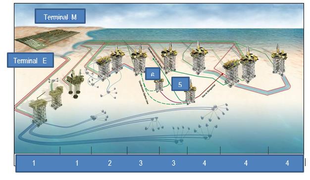
formed that affect its corresponding weight indicators. Weight indicators are adjusted depending on the design stage, starting from the stage of the technical proposal and subsequently at the stages of outline, technical and working design. Moreover, in this process, at each design stage, the relevant geological and geographical conditions for the location of the structure are refined and the characteristics of the reservoir and floating facilities involved in these activities are taken into account. The last place here is also given to the characteristics of the drilling complex and the modules supporting this complex and the corresponding drilling programs. Of no small importance for the price of the structure as a whole is the availability of connections and interaction with neighboring platforms, the number of production lines, its provision with systems for performing the necessary technological operations, including systems for performing water and gas impacts on wells, energy supply, and re-injection of drilling waste into specially drilled for this purpose, wells, submarine pipelines for access to the terminal, etc. All this is shown in Figure 1, from which it is seen that how the existing structures installed in the offshore are interconnected.
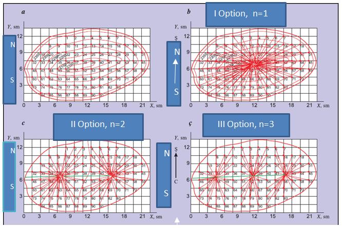
The method of cluster drilling is currently recognized as the most rational and widely used method for developing resources of offshore oil fields [3, 4, 5, 6, 7, 8]. The proposed article describes a project for drilling producing wells using cluster drilling for developing resources from a hypothetical field [4, 5, 6, 9, 10], a structural map of which has an anticlinal tectonic structure is shown on Figure 2a:
Therefore, in this paper, we consider an implementation option for a drilling program for cluster execution, for which evaluation work on the construction of hydraulic structures is given.
Problem Setting
Copyright© Hasanov RA.
Hasanov RA. Identify Possible Clusters on Marine Hydraulic Structures and their Content for the Development of Offshore Hydrocarbon Deposits. Pet Petro Chem Eng J 2019, 3(3): 000203.
Case Study
The longitudinal and transverse dimensions of the field are assumed equal, respectively, up to 2973 and 1707 m. It is assumed that due to the uniform distribution of the natural energy of the field, the well grid of its development is four-point, i.e. the faces of four producing wells are located at the nodal points of a square with a side length of 200m. This means that the area of the oil zone of the wells location is equal to the area of the square with the side length equal to 400 m. = 160000 m2, which means the density of the wells is well / 4g. Thus, on the structural map of the field (see Figure 2), the faces of 91 wells are shown and 6 closed curves are indicated on its roofing part. The vertical difference in the depths of two adjacent closed curves in comparison with sea level is -50 m. The depth of closed curves in the upper part starts from 2100 m. And on the deepest parts of the slopes (near the oil contours) it reaches a depth of 2350 m. Work on the design of well drilling of a hypothetical offshore field, shown in Figure 3 [11], must be performed in the sequence below.
At the beginning, on the structural map of a given offshore oil field, the Cartesian XOU coordinate system is selected as close as possible to the field, the ordinate axis of the system is directed north-south, and the abscissa axis is directed east-west. After this, the values of the X and Y coordinates of all the mine faces of the field in centimeters are measured in this coordinate system and are placed in the table. The numbers of wells are numbered from 1 to 91. To convert the values of coordinates into meters, their values in centimeters are multiplied by a coefficient equal to 133.33. This is a scale factor in which a structural map is constructed that has a unit of measurement of 133.33 m / cm Therefore, after determining the coordinates of the borehole from the structural map, it is necessary to really reflect these coordinates for the field conditions in order to determine its location under these conditions. Therefore, it is necessary to multiply the obtained coordinate values by a scale factor, i.e., by 133.33, which makes it possible to determine these coordinates in meters.
Under sea conditions, hydraulic structures are not allowed to be set arbitrarily, and their number should receive an appropriate justification. In the scientific substantiation of solving the above problems, the main limiting factor is investment and CAPEX, directed to their construction and the volume of drilling operations on platforms. It should be noted that well drilling programs on offshore platforms for the development of reserves of Copyright© Hasanov RA.
Hasanov RA. Identify Possible Clusters on Marine Hydraulic Structures and their Content for the Development of Offshore Hydrocarbon Deposits. Pet Petro Chem Eng J 2019, 3(3): 000203.
the offshore field should be implemented on the condition of a minimum of capital investments. Failure to comply of this condition may cause an increase in prices for the implementation of relevant programs and unreasonable loss of a large amount of funds.
Decision Method
To determine the optimal variant of drilling a given hypothetical offshore field by core drilling, 8 different options are offered, shown in Table 1. As can be seen from the table, the first option envisages the construction of one platform from which all 91 wells with holes will be drilled on this platform. The bottom of all 91 wells are shown on the structural map. Calculated rational coordinates of the platform projection on the structural map, equal respectively to X = 10.86 sm. and y = 6.69 sm [12].
| Version | The Number of Fixed Platforms, N | Number of Wells Drilled from One Platform | ||||||
|---|---|---|---|---|---|---|---|---|
| I | 1 | 91 | ||||||
| II | 2 | 45;46 | ||||||
| III | 3 | 30;31 | ||||||
| IV | 4 | 24;19 | ||||||
| V | 6 | 15;16 | ||||||
| VI | 8 | 12;7 | ||||||
| VII | 16 | 6;1 | ||||||
| VIII | 91 | 1 |
Table1: Consideration of construction options.
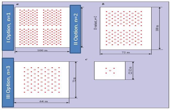
According to these coordinates, the optimal location of the platform projection on the structural map is determined. To simplify the solution of the platform, all the wells are connected to the center of the platform by straight lines (Figure 2b). These lines are projections of directional wells on the structural map. The angles between these lines and the north-south direction are azimuth angles for drilling inclined wells. In this case, the location of all wells to be drilled coincide with the center of the platform. Actually, the layout of the well locations on the platform is represented by the scheme shown in Figure 2c. Here, small points characterize the tower support points of the drilling rig, and circles - the location of the wellheads on the platform. The distance between the wellheads is equal to the distance between the tower supports of the drilling rig, i.e. is assumed to be 8 m. In the second variant, it is planned to build two platforms, and out of 91 wells, 45 wells will be drilled and located on platform I, 46 wells - on platform II (Figure 2c). The coordinates of the platform are presented respectively: Platform I – X1 = 6.27 and Y1 = 6.43 sm; Platform II – X2 = 15.6 and Y2 = 6.95 sm. Thus, the optimal location of both platforms are determined. In Figure 3 shows the layout of the wellheads and tower supports of the derricks on the working site of each platform.
The third option provides for the construction of three platforms. In this option, from 91 wells drilling of 30 wells is supposed to be placed on platform I, 31 wells -on platform II and 30 wells - on platform III (Figure 2c).
The coordinates of the platform are represented respectively: Platform I – X1 = 4.74 and Y1 = 6.2 sm; Platform II – X2 = 10.79 and Y2 = 6.82 sm; Platform III – X3 = 17.05 and Y3 = 7.05 sm. The layout of the wells and derrics tower supports on the working site of each platform is shown in Figure 3. On the structural map, all the bottom holes of the wells corresponding to individual platforms are connected by the central points of the each platforms projections by straight lines, and for the third option, well clusters drilling outline are obtained (Figure 2c). According to the procedure described above, the necessary calculated data for each of the IV, V, VI and VII options were provided. Due to the limited volume of the article, schemes for these options were not presented. For the VIII-th option, due to the verticality of all the provided drilling wells, for each well of a separate platform construction is planned, in which case their number will be equal to the number of wells being drilled, i.e. n = 91. In this case, the platforms projections coincide with the bottoms of the wells being drilled and they do not deviate from the vertical. In each option, to calculate the total costs of well drilling for all wells, it is necessary to start determining the total length of their wells. The location of the vertical bottom hole and only one wellhead outline on the platform working site is determined by the structural map (Figure 2). There may be three different cases: the Copyright© Hasanov RA.
Hasanov RA. Identify Possible Clusters on Marine Hydraulic Structures and their Content for the Development of Offshore Hydrocarbon Deposits. Pet Petro Chem Eng J 2019, 3(3): 000203.
bottomhole of the wells are on one of the iso-hoop (or close to it) curves of the structural map (wells number 1, 10, 17, 25, 26, 30, 34, 49, 53, 55, 58, 65, 73, 84); - the bottomhole of the wells are between the adjacent (or in the middle) iso-hoop curves of the structural map (wells number 3, 12, 15, 19, 36, 42, 46, 54, 61, 76, 86, 89); - the bottomhole of the wells are located between adjacent iso - hoops at different distances from them (this includes all other wells). For bottom holes that correspond to the first case, their vertical depths are not calculated for the definition of their depths, since these depths are assumed to be equal to the depths of the iso-hoops. Due to the equality of the vertical distance between the neighboring iso-hoops is 50 m. in the second case, when calculating the vertical depths of the bottom hole well locations, it is necessary either to add -25 m to the depth of one of the iso hoops, or to take it away from the depth of the other iso-hoops -25 m. The number of wells corresponding to the third case in this field is quite large, which is why the determination of their vertical depths is considerably difficult. For this case, the interpolation method is the most acceptable, using which a straight line is drawn from the bottom of the well to two neighboring iso-hoops. Then this line is measured in mm-ah, which the bottom of the well divides into two parts. By measuring most of this line in mm, the lengths of the obtained sections are determined. For example, the measured length of the line passing through the bottom hole of well No. 5 (the distance between the end points of this line located on adjacent iso-hoops) was 14 mm. On the other hand, the distance measured from this bottom to isohoops, equal to 2350 m, was 9 mm. Thus, the vertical depth of the bottom hole well № 5 was 2336 m. The vertical depths of all wells, calculated according to this procedure, are presented in Table 2 (Table 2). The values of H in all variants are the same
Wells № H, m A, m B, m l2, m L, m Wells № H, m A, m B, m l2, m L, m 1 2354 847 2154 2315 2515 49 2150 647 1950 2055 2255 2 2343 760 2143 2274 2474 50 2112 453 1912 1965 2165 3 2328 720 2128 2247 2447 51 2130 253 1930 1947 2147 4 2321 727 2121 2242 2442 52 2110 100 1910 1913 2113 5 2325 800 2125 2271 2471 53 2140 167 1940 1947 2147 6 2328 900 2128 2310 2510 54 2175 373 1975 2010 2210 7 2336 1040 2136 2376 2576 55 2202 560 2002 2079 2279 8 2332 993 2132 2352 2552 56 2234 773 2034 2176 2376 9 2311 827 2111 2267 2467 57 2264 960 2064 2276 2476 10 2296 680 2096 2204 2404 58 2300 1147 2100 2393 2593 11 2290 573 2090 2167 2367 59 2339 1353 2139 2531 2731 12 2275 513 2075 2137 2337 60 2328 1273 2128 2480 2680 13 2264 533 2064 2132 2332 61 2275 1073 2075 2336 2536 Copyright© Hasanov RA.
Hasanov RA. Identify Possible Clusters on Marine Hydraulic Structures and their Content for the Development of Offshore Hydrocarbon Deposits. Pet Petro Chem Eng J 2019, 3(3): 000203.
| 14 | 2267 | 627 | 2067 | 2161 | 2361 | 62 | 2235 | 882 | 2035 | 2218 | 2418 |
|---|---|---|---|---|---|---|---|---|---|---|---|
| 15 | 2276 | 753 | 2076 | 2208 | 2408 | 63 | 2213 | 670 | 2013 | 2122 | 2322 |
| 16 | 2284 | 913 | 2084 | 2275 | 2475 | 64 | 2209 | 533 | 2009 | 2079 | 2279 |
| 17 | 2307 | 1080 | 2107 | 2368 | 2568 | 65 | 2205 | 380 | 2005 | 2041 | 2241 |
| 18 | 2336 | 1253 | 2136 | 2476 | 2676 | 66 | 2209 | 293 | 2009 | 2030 | 2230 |
| 19 | 2332 | 1087 | 2132 | 2393 | 2593 | 67 | 2222 | 327 | 2022 | 2048 | 2248 |
| 20 | 2291 | 900 | 2091 | 2282 | 2482 | 68 | 2241 | 460 | 2041 | 2092 | 2292 |
| 21 | 2261 | 713 | 2061 | 2181 | 2381 | 69 | 2265 | 627 | 2065 | 2158 | 2358 |
| 22 | 2242 | 547 | 2042 | 2114 | 2314 | 70 | 2283 | 807 | 2083 | 2234 | 2434 |
| 23 | 2239 | 400 | 2039 | 2078 | 2278 | 71 | 2309 | 993 | 2109 | 2331 | 2531 |
| 24 | 2220 | 320 | 2020 | 2045 | 2245 | 72 | 2337 | 1180 | 2137 | 2441 | 2641 |
| 25 | 2206 | 347 | 2006 | 2036 | 2236 | 73 | 2346 | 1333 | 2146 | 2146 | 2346 |
| 26 | 2202 | 467 | 2002 | 2056 | 2256 | 74 | 2310 | 1147 | 2110 | 2402 | 2602 |
| 27 | 2220 | 633 | 2020 | 2117 | 2317 | 75 | 2286 | 973 | 2086 | 2302 | 2502 |
| 28 | 2230 | 813 | 2030 | 2187 | 2387 | 76 | 2273 | 807 | 2073 | 2225 | 2425 |
| 29 | 2240 | 1000 | 2054 | 2284 | 2484 | 77 | 2271 | 660 | 2071 | 2174 | 2374 |
| 30 | 2296 | 1187 | 2096 | 2409 | 2609 | 78 | 2268 | 547 | 2068 | 2208 | 2408 |
| 31 | 2339 | 1380 | 2139 | 2546 | 2746 | 79 | 2273 | 487 | 2073 | 2129 | 2329 |
| 32 | 2343 | 1253 | 2143 | 2482 | 2682 | 80 | 2280 | 513 | 2080 | 2142 | 2342 |
| 33 | 2295 | 1047 | 2095 | 2342 | 2542 | 81 | 2293 | 587 | 2093 | 2174 | 2374 |
| 34 | 2250 | 847 | 2050 | 2218 | 2418 | 82 | 2313 | 740 | 2113 | 2239 | 2439 |
| 35 | 2210 | 653 | 2010 | 2113 | 2313 | 83 | 2333 | 900 | 2133 | 2315 | 2515 |
| 36 | 2179 | 453 | 1979 | 2030 | 2230 | 84 | 2350 | 1233 | 2150 | 2478 | 2678 |
| 37 | 2167 | 267 | 1967 | 1985 | 2185 | 85 | 2335 | 1080 | 2135 | 2393 | 2593 |
| 38 | 2142 | 120 | 1942 | 1946 | 2146 | 86 | 2325 | 933 | 2125 | 2321 | 2521 |
| 39 | 2114 | 187 | 1914 | 1923 | 2123 | 87 | 2319 | 813 | 2119 | 2270 | 2470 |
| 40 | 2128 | 380 | 1928 | 1965 | 2165 | 88 | 2321 | 733 | 2121 | 2240 | 2440 |
| 41 | 2142 | 567 | 1942 | 2023 | 2223 | 89 | 2325 | 693 | 2125 | 2235 | 2435 |
| 42 | 2174 | 767 | 1974 | 2118 | 2318 | 90 | 2332 | 707 | 2132 | 2246 | 2446 |
| 43 | 2219 | 960 | 2019 | 2236 | 2436 | 91 | 2343 | 773 | 2143 | 2278 | 2478 |
| 44 | 2268 | 1153 | 2068 | 2368 | 2568 | ||||||
| 45 | 2321 | 1347 | 2121 | 2513 | 2713 | ||||||
| 46 | 2323 | 1253 | 2123 | 2465 | 2665 | ||||||
| 47 | 2368 | 1033 | 2168 | 2402 | 2602 | ||||||
| 48 | 2213 | 847 | 2013 | 2184 | 2384 |
Table 2: Determination of the option 1 parameters: I Option: n=1: l1 = 200m. Note: H - is the vertical depth of the well; A-dista
Table 2: Determination of the option 1 parameters: I Option: n=1: l1 = 200m. Note: H - is the vertical depth of the well; A-distance deviations of the bottom hole from the vertical; B-vertical height of the curved part of the well bore; l2 - inclined (straight) line, replacing the length of the curved part of the wellbore; L2 - is the length of the borehole model. Due to the difference in the number of platforms in the considered options for the development of field resources by drilling programs, the deviation of the “A” well heads from the vertical is different. To determine “B” - the vertical height of the curved section of the wellbore from the distance “H” - the vertical depth of the well is subtracted l1 = 200 m (Table 2). The values of L2-were determined according to the Pythagorean theorem.
It was taken into account that for wells drilled in the conditions of the Caspian Sea, the cost of one meter of penetration in the SOCAR system a cost of 1,775 $ is estimated. According to this indicator, for various variants of cluster drilling of 91 wells, the total cost of each of them was determined by the following sequence: For option I (n = 1), the total length of all boreholes was 219842 m. Taking into account that the total cost N1 = 219842 * 1775 = 390219550 $; -For option II (n = 2), the total penetration rate for all wells was 213146 m., Taking into account that the total cost N2 = 213146 * 1775 = 378334150 $; - For option III (n = 3), the total penetration Copyright© Hasanov RA.
Hasanov RA. Identify Possible Clusters on Marine Hydraulic Structures and their Content for the Development of Offshore Hydrocarbon Deposits. Pet Petro Chem Eng J 2019, 3(3): 000203.
in all wells amounted to 211345 m., Taking into account that the total cost N3 = 211345*1775 = 375137375 $. Similar calculations were performed for all options, and the results are shown in Table 3, from which it follows that for various well drilling programs, with an increase in the number of platforms, the total length of the planned wells and their total cost decreases.
| Version | Number of Platforms, N. | Total Length of All Wells, M | Total Cost of All Wells, $ | ||||||||
|---|---|---|---|---|---|---|---|---|---|---|---|
| I | 1 | 219842 | 390219550 | ||||||||
| II | 2 | 213146 | 378334150 | ||||||||
| III | 3 | 211345 | 375137375 | ||||||||
| IV | 4 | 210189 | 373085475 | ||||||||
| V | 6 | 208643 | 370341325 | ||||||||
| VI | 8 | 208128 | 369427200 369427200 | ||||||||
| VII | 16 | 207011 | 367680600 | ||||||||
| VIII | 91 | 206144 | 365905600 |
Table 3: Determination of design and cost characteristics of wells.
For the first option, 96 wells can be drilled from the platform, but according to the development project for a given field, 91 wells have to be drilled. The working area of the platform is divided into 4 equal parts with a distance of 12 meters between them, and empty distance for 12 meters length are left at the edges of the platform. 24 wells can be drilled from each part of the platform, but one of them needs to be drilled 19 wells for getting the total number of 91 wells. Due to the presence of the distance between the drilling tower supports and the distance between the well heads are 8 m. the area of the working site of platform will be S1 = 13200 m2. According to statistical data on the Caspian Sea, the average cost of
| Option | Number of Platforms, N | Total Area of Platforms, M2 | Total Cost of All Platforms, Manat. | ||||||||
|---|---|---|---|---|---|---|---|---|---|---|---|
| I | 1 | 13200 | 144276000 | ||||||||
| II | 2 | 12672 | 138504960 | ||||||||
| III | 3 | 13824 | 151096320 | ||||||||
| IV | 4 | 16128 | 176279040 | ||||||||
| V | 6 | 18432 | 201461760 | ||||||||
| VI | 8 | 21504 | 235038720 | ||||||||
| VII | 16 | 30720 | 335769600 | ||||||||
| VIII | 91 | 93184 | 1018501120 |
Table 4: Determination total cost of platforms.
As can be seen from the table, for various well drilling programs as the number of platforms increases, their total area of working sites increases 7 times and therefore the total cost of platforms under construction increases in accordance with the implemented options. Below the sequence of determining the optimal designs of sea pier, (determining metric dimensions) and their costs for various types of cluster drilling is shown. The length of the overpass (sea pier) connecting the location of offshore field with the mainland supposed to be known. We Copyright© Hasanov RA.
Hasanov RA. Identify Possible Clusters on Marine Hydraulic Structures and their Content for the Development of Offshore Hydrocarbon Deposits. Pet Petro Chem Eng J 2019, 3(3): 000203.
assume that this distance is equal to L1 = 2000 m and for the all implemented well drilling options is constant. The remaining parts of the overpass (sea pier), i.e. its main part and extensions are located on the offshore field expectation area and attached to the main area of the platform. On Table 5 the lengths of the overpasses (sea pier) and their cost for all options of the cluster drilling are shown:
| Option | Number of Platforms, N | Total Length of All Trestles, M | Total Cost of All Trestles, $. | ||||||||
|---|---|---|---|---|---|---|---|---|---|---|---|
| I | 1 | 3447 | 37675710 | ||||||||
| II | 2 | 4080 | 44594400 | ||||||||
| III | 3 | 4300 | 46999000 | ||||||||
| IV | 4 | 5367 | 58661310 | ||||||||
| V | 6 | 6247 | 68279710 | ||||||||
| VI | 8 | 6967 | 76149310 | ||||||||
| VII | 16 | 9313 | 101791090 | ||||||||
| VIII | 91 | 20213 | 220928090 |
Table 5: Total cost of all trestles with platforms.
For the first two options, the extentions to the trestles are not made, but its main part consists two sections, namely: the distance from the offshore field to the first I platform and the straight section connecting the I and II platforms. For the third option, additional extentions are also not foreseen, but its main part includes only 3 sections, namely, up to the first platform I, the section connecting platforms I and II, as well as the section connecting platforms II and III. On the fourth option, the main part of the overpass (sea pier) consists two sections and two additional extentions.
Results & Discussion
As can be seen from table 5, with an increase in the number of platforms, for drilling clusters various variants the length and, accordingly, the cost of building the required trestles are increased. The total costs for the construction of marine hydraulic structures (platforms and trestles) for implementation of drilling clusters for various drilling programm options are determined by the below mentioned formula [4]:
$$ N = N _ {w} + N p + N _ {t} (1) $$
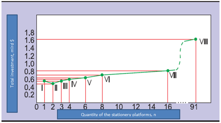
Nw, Np, Nt - respectively, there are costs associated with drilling wells, with the construction of platforms and trestles accordingly, and N - there are total cost (CAPEX) associated with the development of the offshore field. Usually the option with a minimum total investment as an effectiveness option is accepted. The dependence N = N(n), reflecting the change of total expenditures with the number of platforms in Figure 4 is shown.
Copyright© Hasanov RA.
Hasanov RA. Identify Possible Clusters on Marine Hydraulic Structures and their Content for the Development of Offshore Hydrocarbon Deposits. Pet Petro Chem Eng J 2019, 3(3): 000203.
It should be noted that if for the development of reserves of a given field, all 91 wells from three platforms are drilled using the cluster method (n = 3), i.e. if one extra platform is built, then it will require capital investments in the amount of N3 = 573323695 $, i.e. extra costs will amount to 195 mln. $. If all 91 wells for a given field will be drilled from one platform under a well drilling cluster program, then this will require total investments of N1 = 572171200 $, i.e. in this variant of field reserves development (n =1) expenses will be exceeded by the amount of 194 mln $.
Conclusion
- For the adopted 8 options of a given field reserves development using cluster drilling technology with an increase of platforms number , the total length of all wells and their costs decreases.
- In the considered options of a given field reserves development, due to the increase of fixed platforms number, the areas the platform working sites and length of trestles and their extentions, capital investments for the construction of hydraulic structures in sea conditions are usually large.
- With an increase of the number of platforms, total investment for the implementation of cluster drilling and the construction of hydraulic structures, depending on the number of platforms, initially decreases and then increases.
This dependence has one minimum, which corresponds to the option of developing the reserves of a given field with a minimum total investment.
References
-
Nouban F, French R, Sadeghi K (2016) General guidance for planning, design and construction of offshore platforms. Academic Research International 7(5): 37-44.
-
Gumbatov GG, Babaev FA (1999) Repair and maintenance of offshore oil hydraulic structures. Baku, Elm, pp: 188.
-
Mustafaev SV (2013) Method of designing cluster drilling of offshore oil fields. International scientific and technical journal 1: 16-23.
-
Sadeghi K (2008) Significant guidance for design and construction of marine and offshore structure. GAU Journal of Soc & Applied Sciences 4(7): 67-92.
-
Sadeghi K (2013) An overview of design, construction and installation of offshore template platforms suitable for Persian Gulf oil/gas fields. Kyrenia: First International Symposium on Engineering. Artificial Intelligence and Applications.
-
Leffler WI, Pattarozzi R, Sterling G (2011) Deepwater Petroleum Exploration and Production: A nontechnical Guide. 2nd (Edn.), Penn well Corporation, Tulsa, Oklahoma, pp: 1-8.
-
Sadeghi K, Bichi AH (2018) Offshore tower platforms: An over viewer of design, analyses, construction and installation. Academic Research International 9(1): 170-187.
-
Haritos N (2007) Introduction to the analysis and design of offshore structures: An overview. EJSE Special Issue: Loading on Structures, pp: 55-65.
-
Jia J (2017) Modern Earthquake Engineering Offshore and Land–based structures. 1st (Edn.), Offshore Structures versus land - based structures. Springer Verlag GmbH Germany, Germany, pp: 73-106.
-
Muyiwa OA, Sadeghi K (2007) Construction, planning of an offshore petroleum platform. GAU J Soc & Appl Sci 2(4): 82-85.
-
Pedro GSDA (2014) Offshore foundations technologies, design and application. pp: 145.
-
Nouban F, Sadeghi K (2014) Analytical model to find the best location for construction of new commercial harbors. Academic Research International 5(6): 20- 34. Copyright© Hasanov RA. Hasanov RA. Identify Possible Clusters on Marine Hydraulic Structures and their Content for the Development of Offshore Hydrocarbon Deposits. Pet Petro Chem Eng J 2019, 3(3): 000203.
- Nigeria’s Vulnerability in the Face of Global Energy Policy
- A Simulation Study of Investigation of Optimum Oil Production Performance by Applying Various Gas Injection Methods in Oil Reservoir
- Characterization of Permo-Triassic Reservoirs through Thermal Maturity Assessment of Westphalian Source Rocks in the Cheshire Basin
- Influence of Microwax on the Rheological and Thermal Behaviour of a Wax Crude Oil
- Real-Time Monitoring and Performance Optimization of Steam Injection in Heavy Oil Reservoirs Using Fiber Optic Sensing and Integrated Predictive Simulation Models
- Rapid On-Site Determination of the Total Petroleum Hydrocarbon Content of Soils by Handheld Fourier Transform Near-Infrared Spectroscopy: Development of a Global, Site- and Scanner- Independent Calibration Model