A Simulation Study of Investigation of Optimum Oil Production Performance by Applying Various Gas Injection Methods in Oil Reservoir
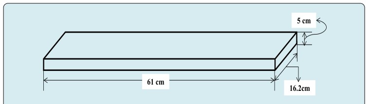
The oil production performance has been a vital key performance indicator to assess the oil reservoir in oil industry. It can be either naturally production which strongly depends on gas expansion energy, or artificially production which depends on external energies such as waterflooding and enhanced oil recovery methods “EOR”. EOR methods depend on the reservoir conditions as well as rock and fluid properties. Based on EOR applications, gas injection has been considered the common method in oil industry in order to increase oil production performance and decrease the environmental pollution. In this paper, a simulation model is created to mimic a lab scale, and its dimensions are 61 cm length, 16.2 cm width and 5 cm thickness. For fluid and rock properties, brine is an aqueous phase, and n-Decane and light crude oil are used as oleic phase, furthermore, the rock is assumed homogeneous and water wet porous media. Using commercial software, several gas injection methods are applied in order to increase oil production performance, and those depend on miscibility levels, stage of gas injection and injection schemes. The oil production performance strongly depends on the viscosity ratio between displaced and displacing fluids. For miscibility factor, fully miscible gas injection has highest oil production performance rather than immiscible and near miscible gas injections. For gas injection schemes, simultaneous water and miscible gas injection scheme is the optimum scheme to produce more oil with less gas consumption. Finally, gas injection at secondary stage is more achievable rather than gas injection at tertiary stage in order to improve macroscopic and microscopic sweep efficiencies.
Introduction
Generally, the production behaviour for immiscible two- phase flow in porous media can be influenced by three factors which are namely fluid properties, gravity and capillary forces Buckley [1] and Leverett [2]. On the other hand, immiscible displacements in porous media strongly demonstrate capillary and viscous forces [3]. The behaviour of two-phase flow in porous media numerically was explained, and they also approved a technique for predicating the movement from sand crude oil by gas or water [4]. They concluded that excellent agreements with oil recovery are observed at and after breakthrough in five-spot model. It was concluded that the displacement is piston-like when the capillary and gravity forces are neglected [5]. A fully implicit method for solving nonlinear equations was furthermore yielded high stability of computation per time rather than implicit pressure and explicit saturation method [6]. Adaptive implicit scheme to solve equations of fluid flow in porous media was observed more efficient than fully implicit as well as explicit [7]. The mathematical solutions using finite difference, semi-analytical, and analytical approaches were matched with the results of imbibition experiments [8]. In addition, those results agreed with published results Christie [9] and Langsrud [10].
The performance of fluid flow inside simulation model can be affected since the chemical interactions between brine and rock can be occurred through desorption and adsorption of calcium, magnesium and sodium [11]. It was observed that thickness of viscous fingers reduces when Peclet number and viscosity ratio increase [12]. The immiscible two-phase flow in porous media strongly depended on three major factors which are gravitational effects, viscosity ratio and permeability [13]. They observed that large fluid-fluid interface relative to fluid-solid area is occurred when the permeability of the porous media is high. In the other hand, there were several factors to decrease fluid-fluid interfacial area momentum exchange, and those depended on pore- size distribution, low permeable porous media, capillary pressure and wettability.
The objective of this paper is found the optimum oil production performance by applying gas injection methods and schemes in both tertiary and secondary stages.
Oil Demand in The Future
The oil demand has been increased with energy demand as shown in Figure 1 [14]. For supplying energy demand, the development strategies are required to create from oil industry, research centres and institutes. These can be intelligent and economic when geological structure in subsurface is clearly understood and evaluated the mechanism of the hydrocarbon reservoir, consequently, the production of hydrocarbon can be optimized which is the target of petroleum engineers.
Gas Pollution and Its Impact on Environment
It is well known that the gaseous emissions have been increased from combustion or venting of natural or associated gas. For example, the gas flaring and burning off undesirable gas produced during oil processing or extraction, as a result, toxic gases and volatile organic compounds production productions are increased. Those gases can be Carbon Dioxide (CO2), Carbon Monoxide (CO), Sulphur Dioxide (SO2), Nitrogen Oxides (NO2) and others. All of those toxic gases can be effect on environment negatively such as climate change, acid rain, air quality degradation, visibility reduction, human being and others. The intelligent method to decrease the gaseous emissions is the captured them, and use them for getting benefits environmentally that can refer to plants, animals and human being. For example, the gases can be captured and inject them inside oil reservoirs to increase oil production performance in oil industry.
![Figure 1: Profiles of Oil Supply from 1996 till 2030 [14].](/fulltextimages/14149/fig_1.jpeg)
Oil Production Performance in Petroleum Engineering
The oil production performance can be passed through three categories inside oil reservoirs. These are called primary, secondary and tertiary oil production performances. In primary oil production performance, the oil reservoir is produced naturally, and this technique strongly depends on the pressure changes between the oil reservoir and wellbore pressure, and this factor relates to drive mechanism of oil reservoir. In petroleum engineering, there have been almost four drive mechanisms which are called natural water drive, gas cap drive, dissolved gas drive and gravity drainage mechanisms. Each mechanism depends on a significant factor for delivering fluid to surface, and this factor could be aquifer for increasing oil pressure, expansion of gas phase from top, dissolution and expansion of gas phase and driven by gravitational forces. When the natural production from oil reservoir reduces till inefficient production, pumping fluid is required in either gas cap or aquifer to increase reservoir pressure. This process is called pressure support which can assist oil to move to production well. To sum up, the oil production in primary stage strongly depends on the geological characteristics of oil reservoir such as oil viscosity, and reservoir pressure. The range of hydrocarbon production in primary is between 5% up to 15% of original oil in place (OOIP).
Once the pressure support process in primary stage is not feasible, the petroleum engineers create decision to elect other techniques that can be more effective to increase production, and this process is namely secondary oil production performance. In this process, the fluid is injected through the oil zone, and different fluids can be utilized to reach the target of petroleum engineers, however, most effective technique is called waterflooding which means that the water is injected in oil zone. At the end of implementing secondary technique in reservoir, the oil recovery can reach to the optimum value which depends on the oil and reservoir characterizations. Some authors reported that the percentage of oil production performance in secondary stage can recover between 15% till 35% of OOIP [15].
Most EOR methods are presented extensively in reference Thomas [16]. The last technique, which relates to enhance oil recovery of reservoir, is called the tertiary oil recovery technique. There have been several methods under this technique such as surfactant flooding, polymer flooding, in situ combustion, microbial flooding and gas injection, etc. For implementing these methods in a real reservoir, screening criteria for selecting the optimum technique from EOR applications require in order to reach the economical and beneficial target project. These criteria can refer to reservoir properties such as depth, rock and fluid properties, temperature and pressure. However, there are two crucial factors that can demonstrate the oil production performance of any reservoirs, and these are the behaviour of oil flow properties and the interaction between rock and fluid inside oil zone. Furthermore, the major aspect of these methods is to maintain oil production from life end of oil reservoir and produce additional oil recovery which can achieve 5% up to 15% of OOIP.
In gas injection method, the minimum miscibility pressure “MMP” is a vital factor for demonstrating gas-oil flow inside porous media. The main factors affecting miscibility are the reservoir fluid composition, reservoir temperature and pressure. There have been three methods that can inject gas phase inside reservoir, and these are namely immiscible, near miscible and fully miscible gas injections. The minimum miscible pressure point can be found using either slim tube experiment or rising bubble experiment. Once the injection pressure is less than minimum miscibility pressure, the displacement is called immiscible gas injection. In immiscible gas flooding, there exists an interface between the two fluid, hence, there also exists a capillary pressure caused by the interfacial tension between the oil and gas. Since the two fluids are immiscible, higher residual oil saturations can be expected rather than near miscible and fully miscible gas injections.
The gas phase can be fully miscible with oil when the gas injection is higher than minimum miscibility pressure. Gas miscible flooding improves oil recovery through gas drive, swelling of the oil (therefore increasing oil volume) and decreasing the viscosity of the oil. Gas mixes in oil mainly as a result of three mass transfer mechanisms; solubility, diffusion and dispersion. Among these three mass transfer mechanisms, solubility accounts for the greater part of the mixing. When miscibility is achieved, the interfacial tension between the gas and the oil is reduced to zero, and the capillary number reaches to infinity, in fact, the residual oil saturation can be the lowest value as well as amount.
There have been several effective schemes to inject gas inside oil zone, those can be Water Alternating Gas “WAG”, Continuous Gas ”CG” and Simultaneous Water and Gas “SWAG” injections. The mechanism of WAG scheme is the gas injection alternating with water as cycles. These cycles relate to water and gas ratio which can be constant during gas and water injection. The purpose of using water in this method can be reduced the gas segregation which can be delayed the breakthrough of displacing fluid. Usually, this method is implemented in stratified heterogeneous reservoirs. The CGI method is defined as the gas is continuous injection inside the oil zone practically, it is usually preferred to implement it in homogenous porous media. In SWAG injection method, both gas and water are injected at same moment and time.
This method has been developed to improve both volumetric sweep efficiency and the project economics. Moreover, for reasons of economics and mobility control, a gas flood is rarely implemented as a “continuous gas injection” process, but rather in slugs with a chase gas or water behind the gas bank. WAG injection inside porous media can support to enhance the sweep efficiency, thus, it can demonstrate the mobility control.
The objective of this paper is found the optimum oil production performance by applying gas injection methods and schemes in both tertiary and secondary stages.
Simulation Model Set Up
Some assumptions are applied in the simulation model, and these assumptions are that the porous media is homogenous so the permeability does not change with space. Furthermore, the water is a wetting phase, and oil phase is non-wetting phase. Moreover, the dimensions of simulation model are illustrated in Figure 2 and Table 1 represents properties of fluid and porous media. Those can be used for simulation computation of two-phase flow inside porous media. The results of them will be explained and discussed in the next section.
| Properties | Values |
|---|---|
| Residual oil saturation | 30% |
| Connate water saturation | 30% |
| Porosity | 20% |
| Density of oil phase | 853 kg/m3 |
| Density of water phase | 1060 km/m3 |
| Permeability | 2.916E-13 m2 |
| Water mobility phase | 9.72E-17 m2/cp |
| Oil mobility phase | 8.75E-16 m2/cp |
| Reservoir pressure | 193.1 bar |
| Viscosity ratio between n-Decane to Brine | 0.84 |
| Viscosity ratio between crude oil to Brine | 8 |
| Viscosity ratio between n-Decane to gas | 6.2 |
| Viscosity ratio between crude oil to gas | 60 |
| The minimum miscibility for n-Decane | 131 bar |
| The minimum miscibility for crude oil | 179 bar |
| Price of gas capture, transport and injection | 2.08E+2 $/MSm3 |
| Reservoir temperature | 60oC |
Table 1: Fluid, Rock and Reservoir Properties.
In this paper, applications of gas injection depend on the minimum miscibility pressure as explained previously. According to Al-Netaifi [17], the calculated minimum miscibility pressures for n-Decane and crude oil are approximately 131 bar and 179 bar respectively. However, the twelve runs are conducted in this paper to investigate the ideal gas injection scenario to optimize oil production performance economically. Table 2 lists all runs, oleic types, injection temperatures, gas injection stages, methods, schemes and pressures and oil recoveries that have been conducted in this paper.
| Run | Oleic Type | Inj. Temperature,oC | Gas Inj. Stage | Gas Inj. Method | Gas Inj. Scheme | Gas Inj. Pressure,Bar | Oil RF, % |
|---|---|---|---|---|---|---|---|
| 1 | n-Decane | 25 | Tertiary | Miscible | CGI | 184.8 | 68.3 |
| 2 | n-Decane | 25 | Tertiary | Near Miscible | CGI | 128.2 | 60.6 |
| 3 | n-Decane | 25 | Tertiary | Immiscible | CGI | 46.8 | 42.8 |
| 4 | n-Decane | 25 | Tertiary | Miscible | SWAGI | 184.8 | 72.8 |
| 5 | n-Decane | 60 | Tertiary | Miscible | CGI | 184.8 | 88.33 |
| 6 | n-Decane | 60 | Tertiary | Near Miscible | CGI | 128.2 | 86 |
| 7 | n-Decane | 60 | Tertiary | Immiscible | CGI | 46.8 | 78.9 |
| 8 | n-Decane | 60 | Tertiary | Miscible | SWAGI | 184.8 | 94.1 |
| 9 | Crude Oil | 60 | Tertiary | Miscible | CGI | 191.3 | 40.1 |
| 10 | Crude Oil | 60 | Tertiary | Miscible | SWAGI | 191.3 | 71.5 |
| 11 | Crude Oil | 60 | Secondary | Miscible | CGI | 191.3 | 93.93 |
| 12 | Crude Oil | 60 | Secondary | Miscible | SWAGI | 191.3 | 83.55 |
Table 2: Summary of Conducted of Various Gas Injection Runs.
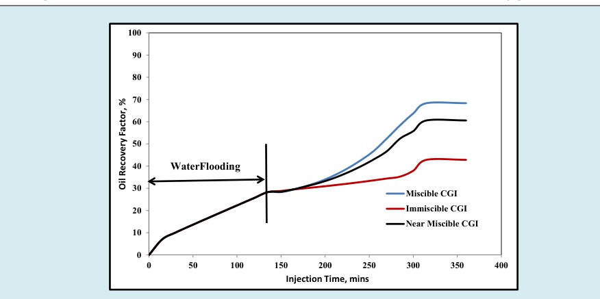
In Figure 3, it is investigated the effect of continuous gas injection pressures on oil recovery factor under ambient temperature at tertiary stage. In waterflooding operation “secondary stage” in Figure 3, the all runs have same oil recovery factor which is 28.3% of Original Oil in Place “OOIP” at 135 minutes. In tertiary stage which is continuous gas injection scheme “CGI”, the fully miscible gas injection “184.8 bar” shows the highest oil recovery factor, which its value is 68.3% of OOIP, comparing with near miscible and immiscible pressures “128.2 bar and 46.8 bar”, and their recoveries are 60.6% of OOIP and 42.8% of OOIP respectively. These results can be referred to two major factors which are namely interfacial between two phases and capillary number. In fully miscible gas injection scheme, the interfacial between two phases is zero so capillary number reaches to infinity that leads to decrease the oil saturation, improve the microscopic sweep efficiency and delay the gas breakthrough. Furthermore, the quality of those factors decreases with decreasing gas injection pressure till reach to the below minimum miscibility pressure “MMP”.
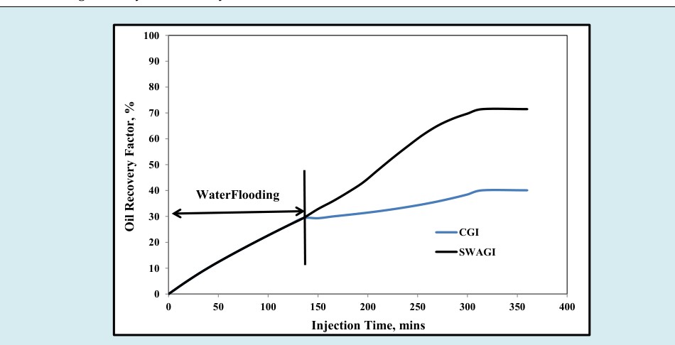
To examine the miscible gas injection schemes for maximizing n-Decane production performance, Figure 4 indicates that the recovery factor of simultaneous water and miscible gas injection scheme “SWAGI” is 72.8% of OOIP comparing with 68.3% of OOIP for continuous gas injection scheme “CGI”. As shown in Figure 4, the n-Decane production performance by miscible gas injection scheme takes more time to improve the microscopic sweep efficiency and physical properties such as solubility, diffusion and dispersion.
While the production performance by simultaneous water and miscible gas injection scheme has a piston like till reach the fluid breakthrough, and this can denote that the miscible gas injection improves the microscopic sweep efficiency and water injection can enhance macroscopic sweep efficiency. Based on Figures 3 and 4, the optimum gas injection scenario to maximize production performance is the simultaneous water and miscible gas injection inside the reservoir, which contains very light component “n-Decane”, at 25oC temperature.
To mimic a real scenario, the injection temperature is a vital factor for gas injection even it can be effect on water injection “waterflooding” as observed in Edmondson [18]. However, the waterflooding process and continuous gas
injection scheme inside the n-Decane reservoir under harsh conditions and various miscibilities are shown in Figure 5. It is indicated that the oil recovery factor by waterflooding process at 60oC temperature is 45.8% of OOIP comparing with 28.3% of OOIP for waterflooding process at 25oC temperature.
This observation due to the wettability alteration of porous media which means that the wettability can alter to strongly water wet porous media.
The oil recovery factor for miscible continuous gas injection at reservoir temperature “60oC” is 88.3% of OOIP, and the miscible gas injection is the optimum scenario to reach the production performance peak, furthermore, this observation agrees with miscible gas injection at ambient temperature “25oC”. On the other hand, the oil recovery factors for near miscible and immiscible gas injections are respectively 86% of OOIP and 78.9% of OOIP.
All trends after 135 minutes in Figure 5 indicate that the gas phase enters inside the reservoir and then reservoir fluid and rock can react with it physically and chemically [11]. As a result, it can improve the solubility, diffusion and dispersion for occurring mass transfer between Miscible SWAGI Miscible CGI Figure 4: Recovery Factor versus Injection Time for Miscible CGI and SWAGI at Ambient Temperature (Runs 1 and 4).
Displacing phase and displaced phase, thus, those factors can probably support displaced phase to flow out from the porous media immediately since the capillary number reaches to infinity.
The implementing of gas injection schemes at reservoir temperature has been a crucial parameter economically. As observed in Figure 6, the oil recovery factor for
simultaneous water and miscible gas injection scheme is 94.1% of OOIP comparing with 88.3 of OOIP for miscible continuous gas injection. Those results agree with observed results at ambient temperature. As mentioned before, the simultaneous water and miscible gas injection scheme has higher oil recovery in order to improve the microscopic and macroscopic sweep efficiencies while miscible continuous gas injection enhances microscopic sweep efficiency.
Based on all previous results, the water injection under reservoir condition in SWAGI schemes can enhance more oil which agrees with Edmondson [18]. In fact, the SWAG scheme is considered to be an optimum scheme to produce the maximum oil recovery, and this result agrees and confirms with Al Eidan, et al. [19].
For representing the realistic case, the miscible gas injection schemes at reservoir temperature are applied on oil reservoir which contains crude oil and its specific gravity 0.853. At waterflooding process “secondary stage”, oil recovery factor of runs 9 and 10 is similar and its value is equal to 29.3% of OOIP at 135 minutes as shown in Figure 7. This value of oil recovery factor is reasonable because the crude oil density is heavier than n-Decane density, and the water breakthrough usually occurs early in the reservoir which has heavy oil.
For miscible gas injection at tertiary stage, the simultaneous water and miscible gas injection scheme is higher oil recovery factor “71.5% of OOIP” than the miscible continuous gas injection scheme “40.1% of OOIP”. These results agree with previous results, and confirm that the ideal gas injection is simultaneous water and miscible gas injection scheme to find the optimum oil production performance since this scheme can improve both macroscopic and microscopic sweep efficiencies. However, the trend of oil recovery factor for miscible continuous gas injection in Figure 7 slightly increases after waterflooding process, therefore, this refers to gravity segregation phenomena and early gas breakthrough occurrence.
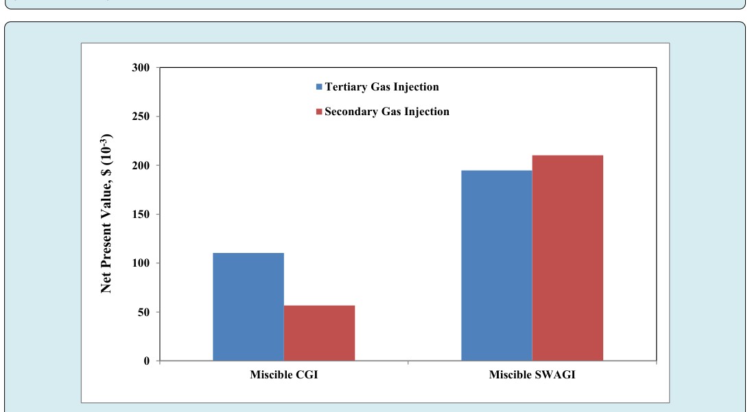
The Figure 8 is indicated that the miscible gas injection schemes at reservoir temperature are applied as a secondary stage. The optimum oil recovery factor is found by applying the miscible continuous gas injection scheme, and its value 93.93% of OOIP, and the oil recovery factor for simultaneous water and gas injection scheme is 83.55% of OOIP. It has been well known that the residual oil saturation at secondary stage is higher than the residual oil saturation at tertiary stage. Thus, the oil recovery factor by applying miscible gas injection schemes at secondary stage is generally higher than the oil recovery factor by applying miscible gas injection schemes at tertiary stage. On the other hand, the gas consumption in a secondary stage is higher than the gas consumption in a tertiary stage. The vital parameter to apply gas injection is the gas availability and supply. In order to study this parameter economically, the Figure 9 shows the economic study for miscible gas injection schemes in both secondary and tertiary stages, and this study is for small scale or experimental scale. In both stages, the simultaneous water and miscible gas injection scheme economically is more benefit comparing with miscible continuous gas injection scheme in terms of gas capture, transport and injection operation and oil price as well.
To sum up, the oil production performance strongly depends on fluid and rock properties and reservoir condition. The oil recovery factor by applying miscible gas injection at reservoir temperature generally increases with decreasing oil specific gravity. Furthermore, the simultaneous water and miscible gas injection scheme in all scenarios has convinced and reasonable oil production performance [19] and high economic benefit as explained in Figure 9.
Conclusions
The simulation study for investigating the optimum oil production performance by applying gas injection methods and schemes in both secondary and tertiary stages has been a crucial element in oil industry. Several conclusions have been investigated in this paper, and those are the following:
- Oil production performance is improved when waterflooding process “secondary stage” applies at reservoir temperature instead of ambient temperature.
- The highest oil recovery factor is occurred at low oil specific gravity by applying gas injection.
- Generally, the miscible gas injection method has highest oil recovery factor comparing with near miscible and immiscible gas injection methods.
- In tertiary gas injection stage, the simultaneous water and miscible gas injection scheme has higher oil production performance comparing with miscible continuous gas injection.
- In secondary gas injection stage, the miscible continuous gas injection scheme has higher oil production performance comparing with the simultaneous water and miscible gas injection scheme. However, the miscible continuous gas injection scheme consumes huge amount of gas phase.
- The simultaneous water and miscible gas injection scheme is concluded the best scheme to optimize oil recovery and beneficial economy in oil industry.
Acknowledgement
The author would like to acknowledge the PE Limited to provide the author a golden opportunity to utilize Reveal Software for finding simulation results of this article.
References
-
Buckley SE, Leverett MC (1942) Mechanism of Fluid Displacement in Sands. Trans 146(1): 107-116.
-
Leverett MC (1941) Capillary Behavior in Porous Solids. Trans 142(1): 152-169.
-
Lenormand R, Touboul E, Zarcone C (1988) Numerical models and experiments on immiscible displacements in porous media. Journal of Fluid Mechanics 189: 165- 187.
-
Douglas J, Peaceman D, Rachford H (1959) A method for calculating multi-dimensional immiscible displacement.
-
Morel-Seytoux HJ (1966) Unit Mobility Ratio Displacement Calculations for Pattern Floods in Homogeneous Medium. SPE J 6(3): 217-227.
-
Allen MB (1986) Numerical modeling of multiphase flow in porous media. In: Advances in Transport Phenomena in Porous Media. Vol 8, University of Wyoming, USA.
-
Blunt M, Rubin B (1992) Implicit flux limiting schemes for petroleum reservoir simulation. Journal of Computational Physics 102(1): 194-210.
-
Cunha L, Bonet E, Cunha J (2004) Experimental Investigation and Numerical Simulation of Water Imbibition in Fractured Turbidite Systems. SPE International Petroleum Conference in Mexico.
-
Christie MA (1989) High-resolution simulation of unstable flows in porous media. SPE Reservoir Engineering 4(03): 297-303.
-
Langsrud O (1976) Simulation of Two-Phase Flow by Finite Element Methods. SPE Symposium on Numerical Simulation of Reservoir Performance, Los Angeles, California.
-
Omekeh A, Evje S, André Friis H (2013) Modeling of low salinity effects in sandstone oil rocks. Vol. 2.
-
Dushin V, Nikitin VV, Legros JC, Silnikov MV (2014) Mathematical modeling of flows in porous media. WSEAS Transactions on Fluid Mechanics 9: 116-130.
-
Pasquier S, Quintard M, Davit Y (2017) Modeling two- phase flow of immiscible fluids in porous media: Buckley-Leverett theory with explicit coupling terms. Phys Rev Fluids 2(10): 104101.
-
Birol F (2008) World energy outlook. International Energy Agency, France.
-
Jayasekera A, Goodyear S (2002) Improved hydrocarbon recovery in the United Kingdom continental shelf: past, present and future. SPE/DOE Improved Oil Recovery Symposium, Tulsa, Oklahoma.
-
Thomas S (2008) Enhanced oil recovery-an overview. Oil and Gas Science and Technology-Revue de l’IFP 63(1): 9-19.
-
Al-Netaifi AS (2008) Experimental investigation of CO2- miscible oil recovery at different conditions. King Saud University, Saudi Arabia.
-
Edmondson TJ (1965) Effect of temperature on waterflooding. J Can Pet Technol 4(04): 236-242.
-
Al Eidan AA, Mamora DD, Schechter DS (2011) Experimental and Numerical Simulation Studies of Different Modes of CO2 Injection in Fractured Carbonate Cores. SPE Enhanced Oil Recovery Conference, Kuala Lumpur, Malaysia.
- Nigeria’s Vulnerability in the Face of Global Energy Policy
- Characterization of Permo-Triassic Reservoirs through Thermal Maturity Assessment of Westphalian Source Rocks in the Cheshire Basin
- Influence of Microwax on the Rheological and Thermal Behaviour of a Wax Crude Oil
- Real-Time Monitoring and Performance Optimization of Steam Injection in Heavy Oil Reservoirs Using Fiber Optic Sensing and Integrated Predictive Simulation Models
- Rapid On-Site Determination of the Total Petroleum Hydrocarbon Content of Soils by Handheld Fourier Transform Near-Infrared Spectroscopy: Development of a Global, Site- and Scanner- Independent Calibration Model
- Isothermic, Kinetic and Thermodynamic Studies of Chromium (VI) Ions Adsorption on Composite Adsorbent of Chitosan- Eggshell Activated Carbon