Numerical Simulation of Multiphase Flow in a Simple Two Phases Separator
Computational Fluid Dynamic (CFD) has been widely used in simulating fluid flows. In this paper, FLUENT 16.2 is employed to perform a numerical simulation of a multiphase flow system. Three different multiphase models, the VOF model, Mixture model, and Eulerian model, have been tested, to find the most suitable numerical model for an oil-water separation system. The velocity distribution, the fields of pressure and oil volume fraction are obtained for three models. The results show that the VOF model has the best separation efficiency among their models. By using the VOF model, the impact of oil concentration and flow rate on separation efficiency has been studied. Furthermore, for the VOF model, the separation process of the VOF model is presented by using phase volume fraction distribution as a function of time.
Introduction
Multiphase flow has rich and complex dynamics, which spread from hydrodynamic to thermodynamics and conservation laws. Many modeling techniques and approaches have been used to model multiphase flow. With the development of computer technique, computational fluid dynamic (CFD) models are developed to model the hydrodynamics of multiphase. Due to its industrial applications, separation of the oil-water system still gains attentions of researches. For oil and water multiphase flow system, most of the studies are focusing on gravity separators and centrifugal separators [1, 2]. These studies use both experimental method and numerical method to study effects of various operating conditions on separation efficiency. Huang S [3] used CFD method to simulate 3-D oil- water turbulent flow by using Reynolds-stress model. In a double-cone liquid-liquid hydrocyclone (LLHC), separation process and separation efficiency had been studied. In oil- water two phase RSM model, Liu, et al. [4] tested the velocity, pressure, and oil concentration distribution of the cyclone separator. This simulation results provided the basis for the improvement and optimization the design of cyclone separator structure. By using CFD method to study gravity separator, Yang, et al. [5] found that liquid viscosity is one of the most important factors that influence the separation efficiency. In Derek, et al. [6] study, they focused the effect of the baffle on separation efficiency for the horizontal separator. Luo, et al. [7] used RSM model to study the impact of velocity, pressure on turbulence flow.
Most of the previous studies about oil-water separation are on turbulence flow and the separator type. Limited research is about oil-water separation process, and which model is more suitable for multiphase flow simulation with FLUENT. Therefore, in this paper, the process of oil-water multiphase flow separation by a gravity horizontal separator is numerically simulated with CFD methods. All three multiphase flow modules in FLUENT are tested based on the separation efficiency. This paper may provide the analytical and numerical foundation for the design and application of multiphase separators at oilfields.
Numerical Simulation Setup
Assumptions
Choose the right multiphase flow model is the first step, and also the defining step in numerical simulation. Oil and water multiphase flow is complex, which means the properties of flow are different throughout the computational domain. In order to apply multiphase flow models into it, the following assumptions are adopted/applied:
- All phases are incompressible;
- Ignore energy losses;
- Assume density and viscosity is constant in calculation domain;
- There is no backward flow in oil and water outlet, which means the gauge pressure at the outlet is 0;
- Transient state analysis is performed for the reported calculation;
- Gravity forces are acting downward along the vertical axis of the separator body;
- Water defined as the primary phase, and oil as secondary phase with 0.2 volume fraction.
Mesh Generation
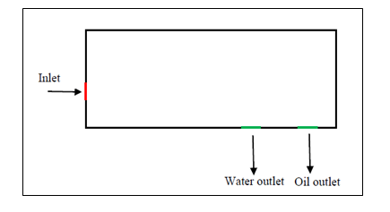
The 2-D two-phase separator model is drawn in this study. The separator with 90” length and 14” high. The schematic diagram of the separator is shown in Figure 1. The inlet pipe diameter is 1 inch and the inlet is 10 inches below the top. The diameter of oil outlet and water outlet are both 1 inch. As show in Figure 1, the geometric model of this separator is achieved by ANSYS16.2. The mesh is generated by quadrilaterals method for face meshing, the interval size of which is 0.01. The total amount of nodes number is 91111, with elements number of 90424. The minimum orthogonal quality of this mesh is 0.8133 and the maximum ortho skew is 0.2865.
Inlet Boundary Conditions
There are three types of inlet boundary conditions are available in Fluent [8], which are mass inlet, pressure inlet, and velocity inlet. For incompressible fluids, mass inlet and velocity inlet has no difference, because for constant density, the velocity inlet boundary condition will fix the mass flow. Pressure inlet can be defined when inlet flow rate or velocity is unknown, or there is no inlet. In this paper, velocity inlet is used in three modules separately.
Outlet Boundary Conditions
More outlet boundary conditions are available for different conditions, among which flow rate and pressure condition are the most commonly used. Outflow boundary conditions are preferable when the velocity and pressure of outlet flow are unknown. Therefore, pressure outlet condition is been used because it often has a better rate of convergence during iteration.
Wall Interface
In the condition of this project, the wall of the separator is set, and the medium in the cell zone is multiphase flow. Furthermore, defined this flow as nonslip boundary condition. Set other parameters, such as roughness, thermal property, etc. as the default value.
Operation Parameters
The densities of oil and water are 780 kg/m3 and 998 kg/ m3, respectively. The kinetic viscosities of them are 0.0024 kg/(ms) and 0.001003 kg/(ms), respectively. The operation gauge pressure is 1 atm, 101350 Pascal, and the temperature is 288.15 K.
Numerical Simulation Results and Discussions
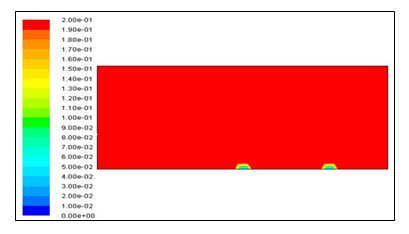
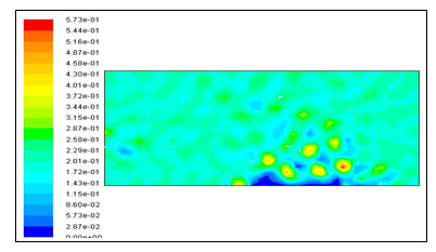
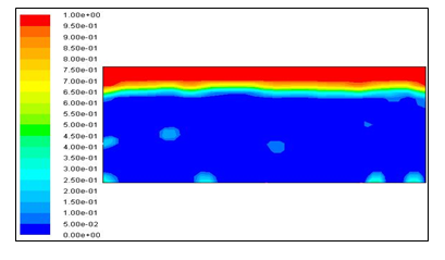
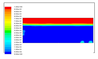
Volume Fraction
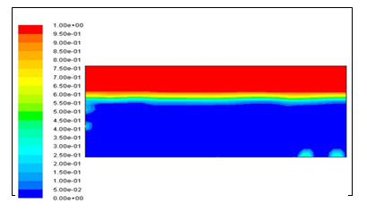
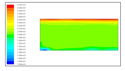
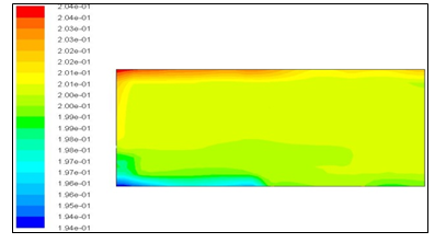
As one of the most important parameters to define the separation efficiency and the performance of the each model, the contours of volume fraction are shown in Figures 2-4. The variation of phase concentration in the separator for three models is shown in these figures. Red and blue colours represent oil and water (i.e. the volumetric fractions of dispersed phase are 1 and 0), respectively. Figure 5 shows the oil volume fraction at the top layer (y=14”) of three models. Comparing these three multiphase flow models, one can find that the VOF model presents the best simulation separation efficiency. As figure 5 shows, oil volume fraction at the top layer starts to increase greatly at the beginner. After 400 s, oil volume fraction almost 1 at the top layer. In Colman’s study [9], he provided a simple way to measure separation efficiency. In his measurement, polypropylene was utilized to substitute oil droplets as the dispersed phase. His results shows that when oil droplet , the separation efficiency is over 95%. In this VOF model, the simulation result is consistent with Colman’s study. However, as contrast, the Mixture model and Eulerian model have poor separation efficiency as show in Figure 3 and 4. This is proved that the VOF model is more suitable for modeling oil-water two phase separation.
Impact of Oil Volume Fraction
Different oil volume fraction will result in the variation of viscosity and density of multiphase flow, thus influencing the separation efficiency. Figure 6 shows the oil volume fraction on the top layer with different oil contents in VOF model. It can be easily seen from figure 6, with the increasing of oil concentration that less time is spent on separation. The reason for this phenomenon is that increasing oil content leads to oil droplets more easily to aggregate to generate larger droplets. Large droplets are will significantly reduce the separation time [10].
Impact of Flow Rate
In the oil industry, flow rate is one of the most frequently changing factors. Different operating flow rate might have a significant influence on separation process. In this numerical study, the oil volume fraction is fixed to 0.2, while volume flow rate is changed from 0.4, 08, to 1.2 GPM.
The oil volume fraction of top lay with different volume flow rate is shown in Figure 7. As can be seen from it, increase flow rate results in decreasing of separation time. This is because, in laminar flow, the higher flow rate will provide larger momentum to oil droplets, therefore, increase the aggregation of oil droplets, so decreasing the separation time. In Ling, et al. numerical study [11], they also found that larger flow rate has better separation efficiency.
The Process of Oil-Water Separation: The variation of phase concentration is shown in Figure 8-12. The residential time for oil and water separation process is 10 min. Separation time t = 0, 30, 120, 300 and 600 s have been chosen. The separation process is presented clearly in VOF simulation model.
![Figure 7: As can be seen from it, increase flow rate results in decreasing of separation time. This is because, in laminar flow, the higher flow rate will provide larger momentum to oil droplets, therefore, increase the aggregation of oil droplets, so decreasing the separation time. In Ling, et al. numerical study [11], they also found that larger flow rate has better separation efficiency.](/fulltextimages/6738/fig_7.png)
Conclusions
Numerical simulation with FLUENT is conducted to model oil and water separation process. By comparing three multiphase models, the VOF model has the best performance when modeling oil- water separation process for laminar flow with a higher volumetric ratio ( = 20%) in the secondary phase. The flow field and volume fraction are acquired in the simulation. For 600 s residential time, VOF
model has separation efficiency of 1. Based on this paper, separation efficiency increased by increasing flow rate. Also, oil volume fraction has positive effect on separation. Higher oil concentration reduces separation time significantly. This study provides basic information about which model is more suitable when simulating multiphase flow.
Acknowledgments
The authors wish to thank the ANSYS help center for their support on the CFD simulation part. The authors are also thankful for the financial support from NSERC and RDC.
References
-
Brentwood Industries S (2001) Oil/water separators- Design & applications.
-
Ted F, Chang ML (2002) Using Computational Fluid Dynamic (CFD) simulation to model fluid motion in process vessels on fixed and floating platforms. IBC 9th Annual Production Separation Systems Conference, pp: 1-10.
-
Si H (2005) Numerical simulation of oil-water hydrocyclone using reynoles-stress modelfor eulerian multiphase flows. The Canadian Journal of Chemical Engineering 83(5): 829-834.
-
Haifei L, Jingyu X, Yingxiang W, Zhichu Z (2010) Numerical study on oil and water two-phase flow in a cylindrical cyclone. Journal of Hydrodynamics 22(5): 832-837.
-
Qin Y (2007) CFD simulation of the inner flow field of the gas-liquid gravity separator. Mechanical Research & Application 20: 72-74.
-
Derek W, Waldie B, Mohamad Nor MI, Hsio Yen L (2000) Baffle plate configurations to enhance separation in horizontal primary separators. Chemical Engineering Journal 77(3): 221-226.
-
Haibing L (2007) CFD simulation of the inner flow field of the gas-liquid measure cyclones. Mechanical Engineer 1: 74-76.
-
ANSYS Fluent Theory Guide.
-
Colman D, Thew M (1980) Hydrocyclone to give a highly concentrated sample of a lighter dispersed phase. International Conference on Hydrocyclones, BHRA, Cambridge, UK, pp: 209-223.
-
Darby R (1996) Determining settling rates of particles. Chemical Engineering 103: 109.
-
Yongtu L, Shengqiu Z, Xiaxue J, Xianqi J, Wang L (2013) Numerical simulation on flow field of oilfield three- phase separator. Journal of Applied Mathematics 6.
- Nigeria’s Vulnerability in the Face of Global Energy Policy
- A Simulation Study of Investigation of Optimum Oil Production Performance by Applying Various Gas Injection Methods in Oil Reservoir
- Characterization of Permo-Triassic Reservoirs through Thermal Maturity Assessment of Westphalian Source Rocks in the Cheshire Basin
- Influence of Microwax on the Rheological and Thermal Behaviour of a Wax Crude Oil
- Real-Time Monitoring and Performance Optimization of Steam Injection in Heavy Oil Reservoirs Using Fiber Optic Sensing and Integrated Predictive Simulation Models
- Rapid On-Site Determination of the Total Petroleum Hydrocarbon Content of Soils by Handheld Fourier Transform Near-Infrared Spectroscopy: Development of a Global, Site- and Scanner- Independent Calibration Model