Analysis and Optimization of Heat Exchange Network in Hydrogenation Unit
Hydrogenation technology has many advantages in light and clean oil products, and has become the most reasonable and effective key technology in the refining industry. However, the hydrogenation reaction process is high temperature, high pressure and hydrogen operation, which consumes a lot of fuel and power, and the energy consumption of the unit is high. Through pinch analysis, the violators of pinch points are identified, and the heat exchange process of the existing hydrogenation unit is optimized and adjusted. Reasonably distribute the heat exchange load of mixed hydrogen oil and low-content oil, improve the final heat exchange temperature of mixed hydrogen oil, reduce the heating load and fuel consumption of heating furnace, strengthen the recovery of inefficient low-temperature potential heat, advance to the design of maximum energy recovery (MER), realize the optimization of cold utility and hot utility, and effectively reduce the energy consumption of hydrogenation unit after optimization. The optimization of heat exchange network of hydrogenation unit significantly improves economic and social benefits.
Fu Zhang1,2, Jinhua Yi2, Guangjun Mei1* and Qinzhi Yuan1
Keywords: Hydrogenation unit; Heat exchange network; Pinch analysis; Optimization; Benefit
Introduction
In recent years, with the increasingly strict environmental protection policies and regulations around the world and the promotion of relevant decision-making arrangements on “peak carbon dioxide emissions and carbon neutrality”, the refining industry is facing increasingly severe challenges. On the one hand, it is necessary to produce clean products that meet the requirements of environmental protection laws and regulations; On the other hand, the pollution discharge in the production process must meet the strict requirements of environmental protection laws and regulations. Hydrogenation technology has many advantages in light and clean oil products, and has become the most reasonable and effective key technology in the refining industry [1, 2, 3, 4, 5]. Hydrogenation reaction process is high temperature, high pressure and hydrogen operation, which requires heating and boosting of raw materials and hydrogen, and consumes a lot of fuel and power. Hydrogenation unit is one of the process units with high energy consumption in the refining industry. Moreover, there is a big difference between the highest energy consumption and the lowest energy consumption of similar hydrogenation units [6, 7, 8], which shows that it is necessary to reduce the energy consumption of hydrogenation units. Therefore, the subject of analysis and optimization of the heat exchange network of existing hydrogenation units is put forward.
Basic Data of a Hydrogenation Unit
An oil hydrogenation unit takes the mixed oil of coking gasoline and coking diesel as raw materials, and carries out hydrodesulfurization, denitrification, deoxidation, olefin and aromatic hydrocarbon saturation and other reactions under the action of catalyst to remove impurities such as S, N and O compounds, and produce refined diesel and other products. The unit mainly comprises a reaction part and a fractionation part. Main equipment includes reactor, tower, heating furnace, pump and compressor, etc. Due to the heat exchange process design and operation problems, the area of some key heat exchangers is insufficient, the heat recovery and utilization of high temperature reaction products is not ideal, the heat exchange temperature of mixed hydrogen oil is low, and the heating load of reaction heating furnace is too large. In addition, the low-temperature heat of the unit is not considered for recycling. The energy consumption of the unit is high, reaching 25.1 kgEo/t, due to all cooling and discarding.
The feed oil is mixed with hydrogen after being boosted by pump, and then enters the reactor after being heated by heat exchange and heating furnace. The reaction product enters the stripping tower after heat exchange and cooling. After removing hydrogen sulfide and light hydrocarbons by steam stripping, the bottom oil of the stripping tower is sent to the fractionating tower. The bottom of the fractionating tower is refined diesel oil, which is sent to the product tank farm after heat exchange and cooling. The fractionating tower adopts a reboiler to reboil, and avoid the problem of water in refined diesel during steam stripping.
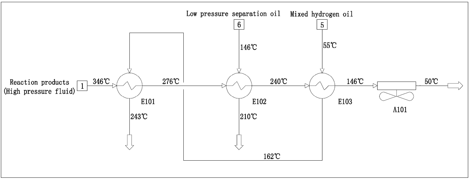
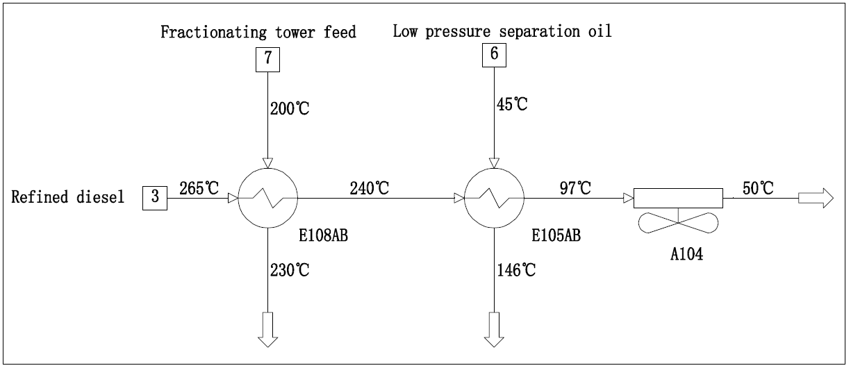
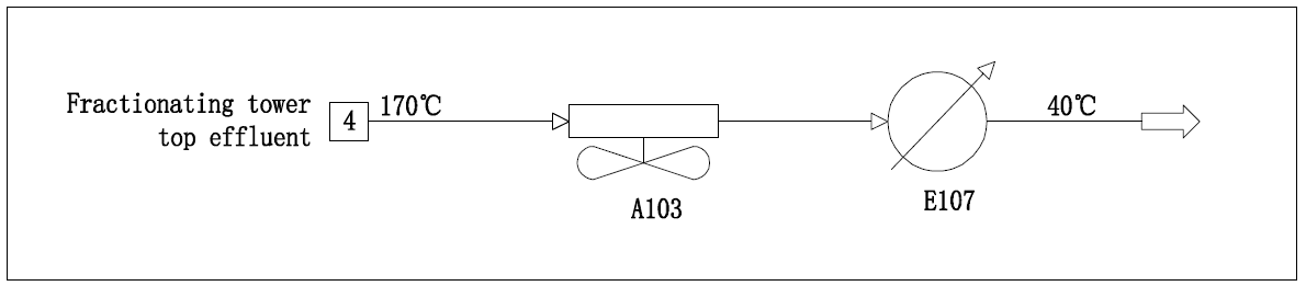
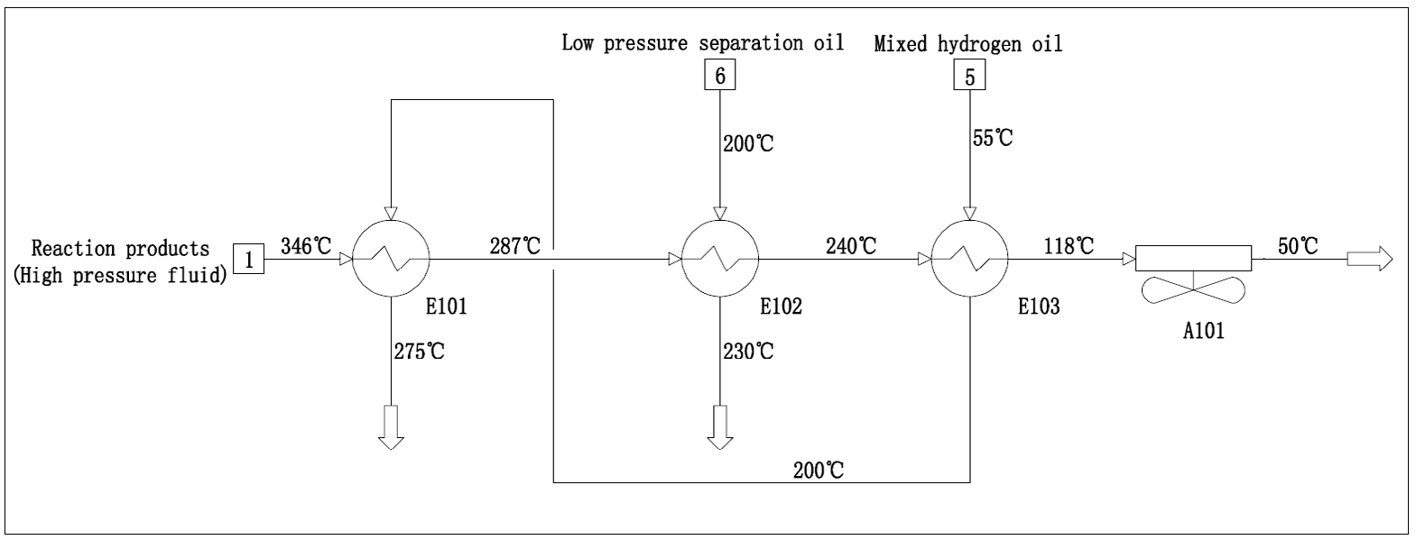
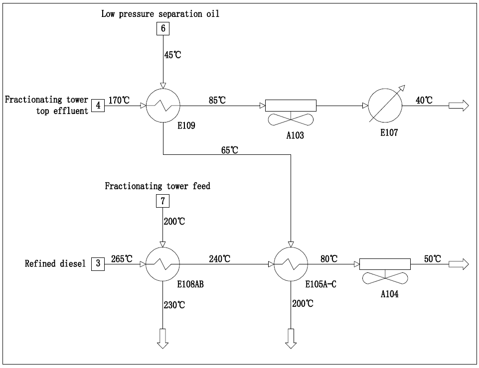
The heat exchange processes of reaction products, refined diesel oil, fractionating tower top effluent, mixed hydrogen oil and low pressure separation oil in this unit are shown in Figures 1-3 respectively.
The cold and hot material flow data extracted from the operating parameters of the unit are shown in Table 1.
| Material Flow Number | Material Flow Name | Flow Rate (t/h) | Initial Temperature (℃) | Target Temperature (℃) | Heating Load (KW) |
|---|---|---|---|---|---|
| 1 | Reaction products | 107 | 346 | 50 | 31261 |
| 2 | Stripping tower top effluent | 15 | 100 | 40 | 360 |
| 3 | Refined diesel | 63 | 265 | 50 | 9327 |
| 4 | Fractionating tower top effluent | 21 | 170 | 40 | 2930 |
| 5 | Mixed hydrogen oil | 105 | 55 | 300 | 22166 |
| 6 | Low pressure separation oil | 84 | 45 | 210 | 9509 |
| 7 | Fractionating tower feed | 83 | 200 | 230 | 2152 |
| 8 | Reboiled oil | 110 | 260 | 300 | 3954 |
Table 1: Cold and hot material flow data of the unit.
Analysis of energy consumption status of the unit
This topic adopts the pinch analysis method, which has been widely used in academic research and industrial practice, and can effectively recover the maximum energy [9, 10].
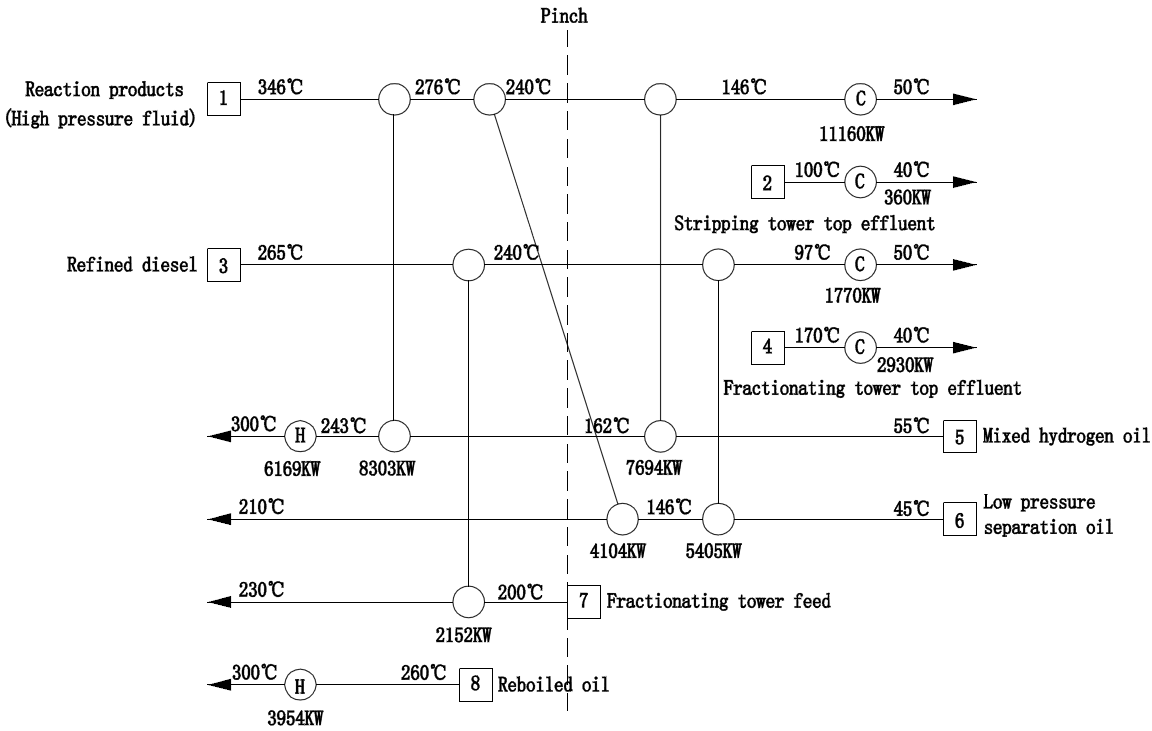
Considering the high investment of heat exchangers and pipelines in the high pressure zone of hydrogenation unit, 40℃ is initially selected as the minimum heat transfer temperature difference in the heat exchange network reconstruction design (which can be adjusted according to the investment situation), and the corresponding pinch analysis of heat exchange network is shown in Figures 4 & 5. The results show that the minimum heat utility is 3450KW, the minimum cold utility is 9547KW, and the pinch temperature is 220℃.The grid diagram of the existing heat exchange network is shown in Figure 6.
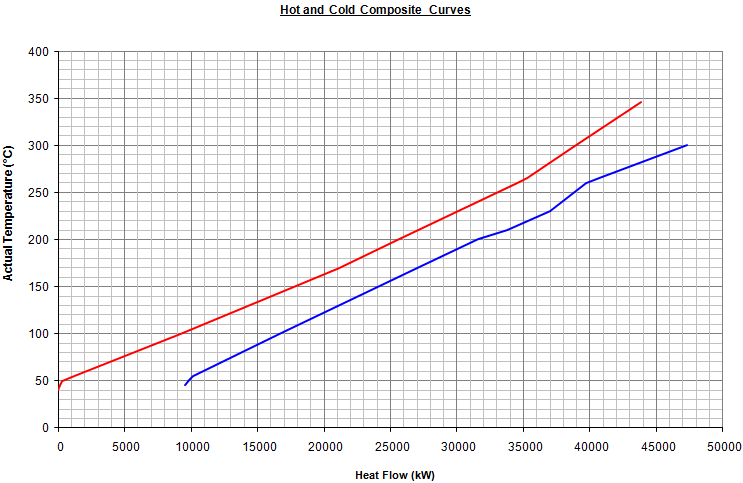
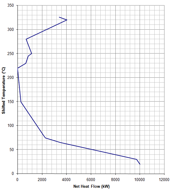
Based on the combined graph of pinch analysis of heat transfer process and the grid diagram of existing heat transfer network, it can be seen that: (1) In the whole temperature range, the temperature difference corresponding to the combined curve of cold and hot flow of the unit is relatively uniform, so it is required that the cross heat transfer with large temperature difference should be avoided in the design of heat exchange network, so as to avoid the heat transfer across the pinch.
(2) A large amount of low-temperature heat in the unit is not effectively recycled, which is directly discharged by air cooling and water cooling, resulting in waste of energy and consumption of a large number of cold utilities, which makes the actual consumption of cold utilities much higher than the minimum cold utilities corresponding to the selected heat transfer temperature difference. Table 2 shows the actual consumption of cold utilities in the unit.
| Material Flow Number | Material Flow Name | Flow Rate (t/h) | Initial Temperature (°C) | Target Temperature (°C) | Heating Load (KW) | |
|---|---|---|---|---|---|---|
| 1 | Reaction products | 107 | 146 | 50 | 11160 | |
| 2 | Stripping tower top effluent | 15 | 100 | 40 | 360 | |
| 3 | Refined diesel | 63 | 97 | 50 | 1770 | |
| 4 | Fractionating tower top effluent | 21 | 170 | 40 | 2930 | |
| add up to | 16220 |
Table 2: Cold utilities actually consumed by the unit.
(3) The actual heat utilities consumed by the unit are much higher than the minimum heat utilities corresponding to the selected heat transfer temperature difference, indicating that there is a large optimization space for the existing heat exchange process. Table 3 shows the actual heat utilities consumed by the unit.
| Material Flow Number | Material Flow Name | Flow Rate (t/h) | Initial Temperature (℃) | Target Temperature (℃) | Heating Load (KW) |
|---|---|---|---|---|---|
| 5 | Mixed hydrogen oil | 105 | 243 | 300 | 6169 |
| 8 | Reboiled oil | 110 | 260 | 300 | 3954 |
| add up to | 10123 |
Table 3: Heat utilities actually consumed by the unit.
(4) From the grid diagram of the existing heat exchange network, it can be seen that the heat transfer between the reaction products and the low pressure separation oil occurs when the heat passes through the pinch point downward, and the existing heat transfer process fails to realize the temperature cascade utilization.
Heat Exchange Network Optimization
Starting from the existing heat exchange network of hydrogenation unit, identify the violators of pinch points, and advance to the maximum energy recovery (MER) design. However, due to the transformation of existing unit, it is often not allowed to make great changes in order to approach the MER design, but can only be compatible with the reference working conditions as far as possible [11, 12].
Due to insufficient heat exchange area between mixed hydrogen oil and reaction products, insufficient heat recovery of high-temperature reaction products, and about 144℃ in air cooling, the final heat exchange temperature of mixed hydrogen oil is seriously low. Therefore, it is considered to add a heat exchanger E103B after E103 in series to enhance heat recovery of reaction products and improve the final heat exchange temperature of mixed hydrogen oil. Reduce the heat load of the reaction heating furnace and the cooling load of the reaction product air cooler from the source.
With the adjustment of heat recovery of reaction products, the heat transfer load distribution of mixed hydrogen oil and low pressure separation oil was optimized. In order to fully recover the heat of refined diesel, a heat exchanger E105C is added after the refined diesel heat exchangers E105A and B, which is connected in series with E105A and B, so as to optimize and adjust the heat exchange load distribution between low-content oil, refined diesel and reaction products, and appropriately reduce the heat exchange load between low pressure separation oil and reaction products.
In order to increase the temperature of low pressure separation oil entering the heat exchange network in the high-pressure zone, so that the heat of reaction products can be more used for heat exchange with mixed hydrogen oil and reduce the load of reaction heating furnace, it is considered to increase the heat exchanger E109 at the top of the fractionating tower, keep the original air cooler and water cooler at the top of the fractionating tower, and exchange heat in series.
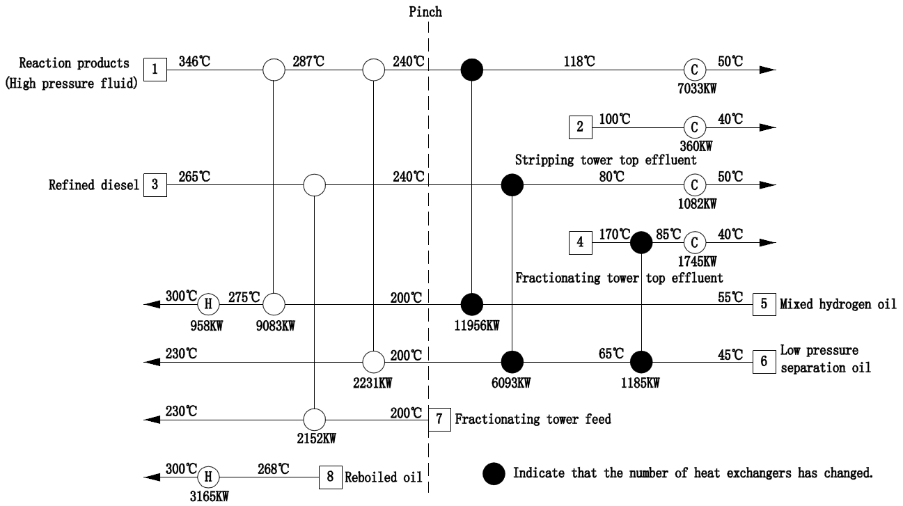
The optimized heat exchange processes of reaction products, refined diesel, fractionating tower top effluent, mixed hydrogen oil and Low pressure separation oil are shown in Figure 7 and Figure 8 respectively.
After the heat exchange process of the unit is optimized and adjusted, the final heat exchange temperature of mixed hydrogen oil increases from 243℃ to 275℃, and that of low pressure separation oil increases from 210℃ to 230℃. The load of the reaction furnace is reduced from 6169KW to 958KW. The heat load of reboiler decreased from 3954 KW to 3165 KW due to the increase of low pressure separation oil temperature. The cooling temperature of the reaction products is reduced from 146℃ to 118℃. The cooling temperature of refined diesel is reduced from 97℃ to 80℃, and the cooling temperature of fractionating tower top effluent is reduced from 170℃ to 85℃. See Tables 4 & 5 for the optimized cold and heat utilities. the cooling load is reduced from 16220KW to 10220KW, and the heating load is reduced from 10123KW to 4123KW.
| Material Flow Number | Material Flow Name | Flow Rate (t/h) | Initial Temperature (℃) | Target Temperature (℃) | Heating Load (KW) | |
|---|---|---|---|---|---|---|
| 1 | Reaction products | 107 | 146 | 50 | 7033 | |
| 2 | Stripping tower top effluent | 15 | 100 | 40 | 360 | |
| 3 | Refined diesel | 63 | 97 | 50 | 1082 | |
| 4 | Fractionating tower top effluent | 21 | 170 | 40 | 1745 | |
| add up to | 10220 |
Table 4: Cold utilities consumed after the unit optimization.
| Material Flow Number | Material Flow Name | Flow Rate (t/h) | Initial Temperature (℃) | Target Temperature (℃) | Heating Load (KW) |
|---|---|---|---|---|---|
| 5 | Mixed hydrogen oil | 105 | 243 | 300 | 958 |
| 8 | Reboiled oil | 110 | 268 | 300 | 3165 |
| add up to | 4123 |
Table 5: Heat utilities consumed after the unit optimization.
The optimized heat exchange network grid diagram is shown in Figure 9. According to Figure 9, there is no cross- pinch heat exchange between reaction products and Low pressure separation oil, and the heat recovery is significantly improved.
After the heat exchange network of the unit is optimized, the existing cold exchange equipment such as air cooler and water cooler remain, and the cooling process remains unchanged to ensure the normal production of the unit. The newly added heat exchange equipment is shown in Table 6.
| Serial Number | Number | Specifications and Models | Number of Units | Investment Estimation (×104¥) | Remarks |
|---|---|---|---|---|---|
| 1 | E103B | DEU900-353-9.8/9.4-6/19-2I | 1 | 136 | add |
| 2 | E105C | BES800-2.5-160-6/25-4 I | 1 | 24 | add |
| 3 | E109 | BIU1000-2.5-425-6/19-4 | 1 | 33 | add |
| add up to | 3 | 193 |
Table 6: New heat exchange equipment after the unit optimization.
Implementation Effect of Optimization
After optimizing the heat exchange process, the heat load of the heating furnace can be saved by about 6000KW, the heat efficiency of the heating furnace is calculated by 90%, and the calorific value of the fuel gas is calculated by 11000 KW/t, so the fuel gas can be saved by 606 kg/h. According to the processing time of 8,000 hours/year, the fuel gas is saved by 4,848 tons/year, which means that the energy consumption of the unit is reduced by about 7.28 kgEo/t, and the annual economic benefit of energy saving exceeds 10 million yuan.
By optimizing and adjusting the heat exchange process of the existing hydrogenation unit, the coordination between heat exchange recovery and heating load of heating furnace is realized. Reasonable distribution of heat transfer load between mixed hydrogen oil and Low pressure separation oil can effectively recover the heat of reaction products, improve the final heat transfer temperature of mixed hydrogen oil, and reduce heating load and fuel consumption of heating furnace. On the premise of ensuring product quality, the steam stripping and fractionation processes are integrated and optimized with the heat exchange network to improve the operation flexibility of the heat exchange network of the hydrogenation unit, which can effectively reduce the energy consumption of the hydrogenation unit and significantly improve the economic and social benefits of the hydrogenation unit.
References
-
Zhang F, Ren Y, Yang M (2019) Industrial application and trend of hydrogenation technology for inferior heavy oil. Modern Chemical Industry 39(6): 15-20.
-
Li DD, Nie H, Sun LL (2016) Hydrotreating process and engineering. 2nd (Edn.), China Petrochemical Press, Beijing, China.
-
Zhang F, Yuan QZ, He K (2021) Status and prospect on processing and utilization of slurry bed hydrogenation solid residue. Industrial Minerals & Processing.
-
Peng Chong, DU Yanze, Feng Xiang, et al (2018) Research and development of hydrocracking catalysts and technologies in China. Frontiers of Chemical Science and Engineering 12(4): 867-877.
-
Swedish International (2006) Development Cooperation Agency. Applying Cleaner Production to Mutilator Environmental Agreements. United Nations Environment Program.
-
Fang XC, Zhang Y (2008) Energy utilization analysis and energy-saving measures of hydrocracking units. Chemical Industry and Engineering Progress 27(1): 151-156.
-
Johonson J (2007) LCO Upgrading: Unlocking High- Value Xylenes from Light Cycle Oil. NPRA Annual Meeting AM-07-40, USA.
-
Brierley GR, Gembicki VA, Cowan TM (2006) Changing Refinery Configuration for Heavy and Synthetic Crude Processing. NPRA Annual Meeting AM-06-16, USA.
-
Linnhoff B, Hindmarsh E (1983) The pinch design method for heat ex- changer network. Chem Eng Sci 38(5): 745-763.
-
Gadalla MA (2015) A new graphical method for Pinch Analysis applications: Heat exchanger network retrofit and energy integration. Energy 81: 159-174.
-
Kemp IC (2007) Pinch analysis and process integration: A user guide on process integration for the efficient use of energy. 2nd (Edn.), Butterworth-Heinemann, Oxford, UK.
-
Li BH, Castillo YEC, Chang CT (2019) An improved design method for retrofitting industrial heat exchanger networks based on Pinch Analysis . Chem Eng Res Des 148: 260-270.
- Nigeria’s Vulnerability in the Face of Global Energy Policy
- A Simulation Study of Investigation of Optimum Oil Production Performance by Applying Various Gas Injection Methods in Oil Reservoir
- Characterization of Permo-Triassic Reservoirs through Thermal Maturity Assessment of Westphalian Source Rocks in the Cheshire Basin
- Influence of Microwax on the Rheological and Thermal Behaviour of a Wax Crude Oil
- Real-Time Monitoring and Performance Optimization of Steam Injection in Heavy Oil Reservoirs Using Fiber Optic Sensing and Integrated Predictive Simulation Models
- Rapid On-Site Determination of the Total Petroleum Hydrocarbon Content of Soils by Handheld Fourier Transform Near-Infrared Spectroscopy: Development of a Global, Site- and Scanner- Independent Calibration Model