Heavy and Ultra-heavy Oilfield Development via Well Borehole Heating
This paper considers the problem of exploitation of fields containing heavy and ultra-heavy oil. The work contains a classification and methods of exploitation of such deposits for all regions of the world containing similar resources. For the production of such oil, it is proposed to create and use a thermolift in the wells to improve the efficiency of the fields and well operation. The possibility of using a thermal elevator in the wells is proposed. To create a thermal elevator in wells it is proposed to use electrochemical generators with solid oxide electrolyte. The constructive scheme and its justification for the use of such batteries in wells are given. Electrochemical generators are resource-saving, environmentally friendly and explosion-proof devices using different types of fuel. Two options of creating a thermolift by using electrochemical generators with solid oxide elements are considered.
Introduction
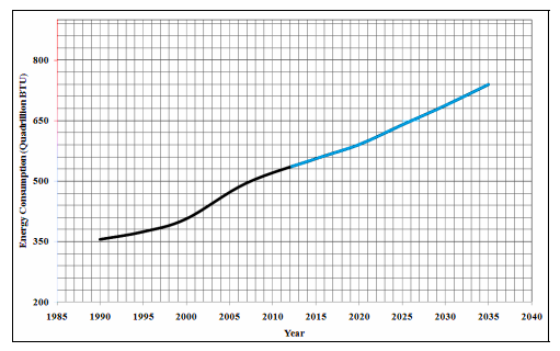
Constant rising global demand for energy is related to economic development and rapid population increase enshrined in the last decades which resulted in a decrease of the oil resources availability characterized by more efficient production and refining. These resources consisted broadly of conventional oil reserves, market cost, production and refining of these consists of technically processing methods. Forecasts predict that the constant global expansion of the energy consumption should last at least until 2035 as stated by the US Energy Information Administration (Figure 1).
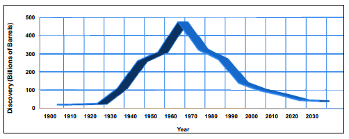
The analysis of the oilfields production capacity showed that conventional oil reserves, both lightweight and medium, reached their maximum in the beginning of the 1960s (Campbell and Laherrere, 1998). Since that time, those reserves continued the constant decrease, so they will probably represent only a small part of the total oil resources available in the nearest future (Figure 2) [1]. Currently, new discoveries of conventional oil are few and insufficient to meet the increasing demand for energy.
The result of this process is a wide gap in the global energy supply with global economic impact. The solution to this issue depends on the ability of the oil industry to transform potential resources into commercially operated reserves.
As a consequence, the development of new technologies has become decisive for profit-making recovery of unconventional resources such as heavy and ultra-heavy oil [1]. Heavy oil is highly viscous oil with an increased density, which due to its physical properties cannot be extracted to the surface with conventional methods. Potential global resources of heavy oil (HO) and natural bitumen (NB) are comparable, and under some estimates they exceed reserves of conventional ones or so-called lightweight oil.
Furthermore, the specific gravity of HO and NB in the structure of hydrocarbon raw materials is steadily increasing. Heavy oil and natural bitumen are essential alternative sources of hydrocarbon fuel which can partially or completely substitute for natural “inartificial” oil. However, the industrial development of effective methods for heavy oil recovery is a complex scientific -technical and feasibility issue.
Speaking of heavy oil they also mean ultra-heavy oil, natural bitumen, i.e. oil with a density of more than 0,920 g/cm3. There are asphaltene-resin substances, nitrogen, chlorine, oxygen and sulphur-containing compounds, as well as metals in heavy oil, especially in natural bitumen, in much larger quantities than in lightweight oil. The greatest cluster of heavy oil reserves is located on the borders of geological pools. It is believed that such oil is the residue of more lightweight oil which has lost its low molecular weight components due to the destruction by bacteria, washing out with water and evaporation. It is estimated that heavy oil reserves on our planet exceed conventional ones more than double.
This article describes the classification and dislocation, states problems and ways to solve the increase in the efficiency of heavy and ultra-heavy oil production, in particular, it considers “the thermolift method”.
Setup of Task
Classification of Heavy and Ultra-Heavy Oil
In classifying oil by their viscosity, a number of scientists established their ambiguity and heavy reliance on density. Thus, some or other intervals of viscosity simultaneously include intervals by oil density as well. In relation to this, the research of dependency of high oil viscosity on their density stands abundantly clear. Plotting such dependencies for vast regions of oil production would allow to get regularities and to study physico-chemical nature of viscosity of highly viscous and ultra-viscous oil.
According to the classification widely used in the global practice [2], heavy oil are hydrocarbon liquids with a density of 920-1000 kg/m3 and a viscosity from 10 to 100 mPa▪s, and natural bitumen are low-flowing or semisolid mixtures of principally hydrocarbon composition with a density of more than 1000 kg/m3 and a viscosity of more than 10000 mPa▪s. An intermediate group between bitumen and heavy oil is formed by so-called ultra-heavy oil with a viscosity from 100 to 10000 mPa▪s and a density of approximately or slightly more than 1000 kg/m3. Many authors unite heavy and ultra-heavy oil under the general title “heavy oil or highly viscous oil”.
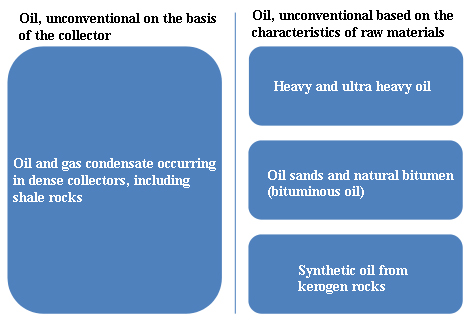
There are certain contradictions in the terminological designation of unconventional oil in the global practice. Thus, in this work, taking into consideration the existing experience [3, 4, 5, 6], a general classification of unconventional oil is presented by the key features of their occurrence and development from the Energy Research Institute of the Russian Academy of Science.
Generally, unconventional oil are considered to be oil reserves development of which by conventional methods is ineffective either due to non-standard conditions of their occurrence (in dense and low-permeability collectors) or because the mixtures extracted from the deposits significantly differ with their physico-chemical characteristics (in particular, by the state of aggregate) from conventional oil mixtures which limits the possibility of their transportation through oil pipelines and processing at an oil refinery plant, and it requires specific ways to prepare them for refining and transport. Thus, there have been two features of “unconventionality” of oil (Figure 3) [7].
Dislocation of Heavy and Ultra-Heavy Oil
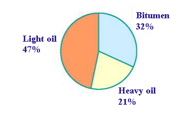
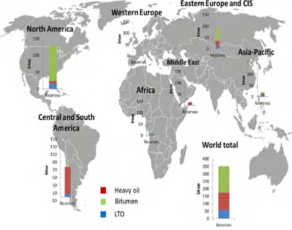
According to various estimates, the reserves of highly viscous heavy oil and natural bitumen range from 790 billion tons to 1 trillion tons which is 5-6 times more than the remaining recoverable reserves of oil with low and medium viscosity amounting to approximately 162 billion tons. Proved reserves of heavy oil and natural bitumen are much less but reserves of lightweight and medium oil are still more known at this time (Figure 4).
According to the information by the US Geological Survey (USGS) [8] and EIA [9] the global technically recoverable reserves of unconventional oil are estimated at over 200 billion tons of oil equivalent which is comparable to similar reserves of conventional oil. More than 2/3 of deposits of unconventional sources are concentrated in North and South America (Figure 5).
The reserve assessment and classification depend on a huge number of factors, the most crucial of which are availability of geological data and background of experience obtained during the direct development of deposits. Taking into consideration that the development of unconventional resources is most actively evolving in North and South
America (for South America, while mainly at the stage of experimental-industrial projects), they are mostly studied and recoverable reserve levels are highly estimated. It’s high probable that as geological exploration and technology transfer to other regions of the world, the available reserves of unconventional oil will grow. The cumulative global production of unconventional oil as of 2017 amounted to about 424 million tons, which corresponds to 9% of the total global production of liquid hydrocarbons. It is worth noting that a huge part of this production, over 350 million tons, took place in North America. The second largest production region with 60 million tons was South America [9].
Issues for Development of Heavy and Ultra- Heavy Oil Fields
Production, transportation and refining of heavy oil represent a major challenge. In particular, to reduce pressure and required capacity for pumping highly viscous oil through oil pipeline, it should be either diluted or heated [10].
Petroleum condensate usually serves as a diluent. Recovery, transportation difficulties, as well as cost increases for refining and purification of raw materials and petroleum products obtained from the high levels of sulfur compounds lead to the noticeable reduction in the costs of heavy oil on the market. Nonetheless, the production of such oil in some regions has become more and more relevant, and considerable attention has been given to the enhanced oil recovery methods of hard-to-recover reserves. The development of heavy and ultra-heavy oil is also complicated by the solution of a number of ecological issues, such as toxic emissions to air, containing sulfur and metal compounds, significant water intake from water reservoir with its further purification, the need for neutralization and utilization of oil sludge etc.
The high viscosity and low density of heavy oil are usually at the heart of the concerns of the development team when considering process components and operating methods. However, there are many negative stories related to the flow assurance issues that should also be taken into consideration in the detailed design. The impact of asphaltenes, paraffins, naphthenates, inorganic deposits and emulsion stability are just some of the most common issues that can and should be solved before the detailed design [11].
Heavy oil (HO) requires the use of intensive technologies of production, as well as expensive and energy-intensive thermal methods. Particular challenge arises in the highly viscous oil production (HVO); currently, many fields of natural bitumen (NB) fall in the latter category as well [12].
So even though there are large fields of natural bitumen in the distributed subsoil fund, their industrial development is proceeding at too low rate. One of the main reasons is the low profitability of their development and the lack of their processing capacity. The self-cost of the production, transportation and refining of heavy oil as compared with conventional oil is higher, and the quality of marketable oil and the products of its processing is lower. Reduced operating costs and increase in the competitiveness of the production is achieved with the use of effective technologies, principally innovative equipment and economic incentive measures [13].
Proposed Solutions to Develop and Increase Efficiency of Heavy and Ultra-Heavy Oil Production
There are various methods of development of heavy oil and natural bitumen deposits that differ in technological and economic characteristics. The application of one or another development technology has been conditioned by the geological structure and bedding conditions, physico- chemical properties of the reservoir fluid, condition and reserves of hydrocarbon raw materials, climatic -geographical conditions etc. They can be conditionally subdivided into three [14] groups that are unequal in terms of implementation scope: a) A complex of hydrocarbon production methods together with their host rock and further separation out-of- reservoir conditions, then ex-situ (it is basically applied in the production of natural bitumen);
b) A complex of impact methods for hydrocarbons inside the reservoir, then in-situ (applied both in the extraction of hydrocarbons from natural bitumen and in the development of heavy and ultra-heavy oil deposits);
c) Quarrying and mining production methods. Those technologies were developing in the 60s and 70s, but they almost have disappeared after losing the competition to a much simpler and safer quarrying method. Nowadays, Yaregskoye oil-titanium field of LUKOIL group is probably the only one in the World that is developed by mining method.
Short wells are drilled from sub-mains located directly in the reservoir, with the help of which oil is recovered and collected into reservoirs, and then rises to the surface. Presently, a more efficient thermal mining method is being implemented. It should be noted, however, that the main product of the mines is titanium ore, and oil is only a sub- product (Figure 6).
![Figure 6: The classification of heavy and ultra-heavy oil and natural bitumen (oil sands) production methods [7].](/fulltextimages/8063/fig_6.png)
Quarrying and Mining Methods of Development
When using the quarrying method of development, the rock saturated with bitumen is extracted by the open method, and, therefore, the possibility of applying this method is limited by the bedding depth up to 50 meters. In using this development method, the main and operating costs on the field are relatively low, but after the rock extraction, extra works are required to extract hydrocarbons from it, which, however, provides a high coefficient of oil recovery: from 65 to 85%.
The mining development can be conducted in two modifications: the mine-purifying one [14] with the rise of hydrocarbon-saturated rock to the surface and mining- borehole one [15] with the guiding of mine workings in the above-bed rocks and the drilling of vertical and sloping well clusters from them to the productive reservoir to already collect oil in mine workings. The mine-purifying method is applicable only to a depth of 200 meters, but it has a higher coefficient of oil recovery (up to 45%) as compared with borehole methods.
The large volume of penetration on barren rocks reduces the method profitability, which is currently cost- effective only if the rock also contains rare metals (except for hydrocarbons). The mining-borehole development method is applicable at deeper depths (up to 400 meters), but it has a lower oil recovery coefficient and requires a large amount of drilling in barren rocks. Steam flooding is used on the reservoir in order to increase the rate of production of HO and NB and to ensure the completeness of the reserve development in the mining-borehole development method [14]. The so-called thermal-mining method is applicable at depths of up to 800 meters, it has a high oil recovery rate (up to 50%), but is more difficult to control than the mining and mining-borehole methods. The most famous example of the mining-borehole development of heavy oil deposits is the Yaregskoye field development. The Yaregskoye field is located in the central industrial region of the Komi Republic, 18 km south-west of the city of Ukhta (Figure 7).
![Figure 7: Scheme for oil recovery from natural bitumen with the quarrying method [16].](/fulltextimages/8063/fig_7.png)
All large volumes of heavy oil, ultra-heavy oil and oil produced from petroleum bitumen (sand) are produced by in-situ technologies, and besides, this tendency is so stable that many global research organizations [17, 18], has begun to classify heavy, ultra-heavy oil and petroleum bitumen into the same category due to the technological and economic similarity of production methods. This study contains only a general description of the key approaches to the development of unconventional deposits. Practically, the involvement of unconventional oil into operation in each individual case is a scientific and practical issue requiring a separate study for each specific deposit, and often during the process of its development.
Since the applicability of ex-situ methods is naturally limited, the methods of in-situ stimulation of hydrocarbons, well-known as in-situ, are increasingly important for the development of vast resources of heavy oil and natural bitumen, as well as [7]: 1) Methods of thermal impact on reservoir: a) Cyclic steam injection; b) Steam gravity drain; 2) Methods of in-situ combustion; 3) CHOPS method.
Thermal Impact
One of the technological directions of enhanced oil recovery is the thermal impact on reservoir [19]. The rise in temperature decreases viscosity and increases the mobility of oil, intensifying its inflow into the productive well. Firstly, such methods were tested in conventional oilfields; however, they were not widely disseminated due to insufficient growth of oil recovery as compared with conventional development methods. The transfer of this technology for the development of reserves of heavy oil and natural bitumen proved to be much more effective, resulting in increase of the anticipated hydrocarbon recovery coefficients by several times as compared to conventional methods. Currently, two main methods of thermal impact with the use of steam as a heat transfer medium dominate: 1) Cyclic steam injection; 2) Steam gravity drain.
The choice of the development technology is generally dictated by the characteristics of a particular deposit. However, a common limit for both methods is the reserve occurrence depth of at least 200 meters. Since, the technology means the injection of overheated steam under high pressure, insufficient depth of the deposit can lead to steam breaking to the surface. Moreover, thermal technologies differ in the high fuel consumption (in general, natural gas) required for preheating of the heat transfer medium.
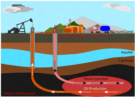
Cyclic Steam Injection: The oldest method of heavy oil recovery in the modern oil recovery practice is cyclic steam injection method. Technology involves alternating the cycles of stimulation of the bottom-hole reservoir zone with hot steam and oil production. Such cycles can last for months (Figure 8).
![Figure 8: Scheme for the development of field using the method of cyclic steam injection. This method is distinguished by its comparative technological simplicity and is not specific to the reservoir characteristics. Thus, the use of one vertical well means the small reservoir coverage by heating and, accordingly, low recovery coefficient is at level of 15-25% [20]. Ax extra shortage is the process cyclically, which basically means prolonged downtime in the production in first and second cycle phases. The method of the cyclic steam injection has been rather limited, providing only about 15 million tons of oil in the World by 2017.](/fulltextimages/8063/fig_8.png)
Figure 8: Scheme for the development of field using the method of cyclic steam injection. This method is distinguished by its comparative technological simplicity and is not specific to the reservoir characteristics. Thus, the use of one vertical well means the small reservoir coverage by heating and, accordingly, low recovery coefficient is at level of 15-25% [20]. Ax extra shortage is the process cyclically, which basically means prolonged downtime in the production in first and second cycle phases. The method of the cyclic steam injection has been rather limited, providing only about 15 million tons of oil in the World by 2017.
Steam-Assisted Gravity Drainage (SAGD): Steam-Assisted Gravity Drainage or SAGD is the further development of cyclic steam injection technology. SAGD means drilling of two horizontal wells, parallel located, about 5 meters apart from each other. The upper one is used for pumping the steam into the reservoir and forming the steam chamber with high temperature, the lower one is used for the production of heated mixture of oil and water (Figure 9).
SAGD technology development has overcome the main disadvantages of the cyclic steam injection method, making the production constant after pre-heating stage and bringing the oil recovery coefficient up to significant 40-60%. The advantages of the SAGD are primarily reflected in the scale of implementation of this method.
In 2016, over 64 million tons of heavy oil was recovered with this method, almost as much as a career method [21]. There are certain requirements for the reservoir structure for the effective application of the SAGD. In particular, the reservoir should have a great deal of capacity and be uniform over a horizontal site with a length of several hundred meters. Taking into consideration the vast reserves of Canada, the main center for implementation of this technology, these restrictions have not yet become serious, however, when transferred to other geological conditions, this might become a significant obstacle [22].
In-Situ Combustion
In-situ combustion is a perspective method for the field development. The technology is based on the initiation and maintenance of combustion processes of hydrocarbons in- situ using the oxidizer injection (air, oxygen). Combustion processes provide the reservoir heating, cracking of heavy fractions, increase of in-situ pressure and oil mobility (Figure 10) [23].
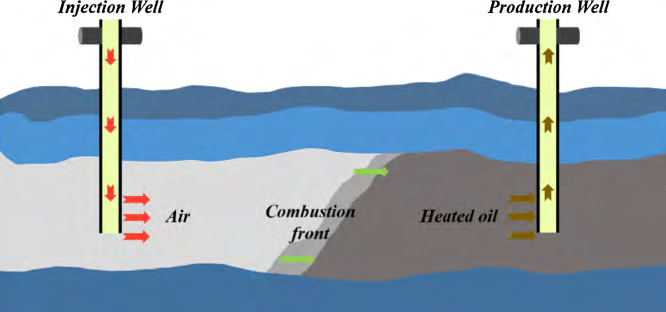
Theoretically, this method should provide oil recovery coefficient up to 50% and partial oil renewal in reservoir conditions. However, as of the beginning of 2019, the technology is at an early stage of the development and there are only few examples for successful implementation [24].
CHOPS (Cold Heavy Oil Production with Sand) Method
A special case among other methods of development of the fields of heavy oil and petroleum bitumen is a method of cold heavy oil production with sand, i.e. CHOPS. This method cannot be classified unambiguously as in-situ, or ex-situ, although the production is carried out inside the reservoir (in-situ), the mixture of oil raw materials and sand coming to the surface needs to be separated similar to the products of the quarrying development. When using the conventional production, the entry of sand and oil containing rock fragments into the well fluid is highly undesirable, since it results in abrasive damage to operating pipes and mechanisms. However, during the development of heavy oil contained in the non-consolidated sandstones, it was detected that the use of shielding leads to a rapid drop in permeability of bottom-hole zone and the corresponding reduction in the production rate up to a complete shutdown of the production, while the extraction of the oil-related sand helps maintain high production levels for longer and achieve relatively high coefficients of oil recovery. The development and introduction of pumps and pipes with the resistance to mechanical damages that allow the unimpeded pumping of multiphase mixtures in the 1980s and 1990s removed the main technological restriction for such a production method.
Thus, the CHOPS method includes the deliberate initiation of sand inflow during well injection with the formation of a network of highly permeable wormholes in the bottom-hole reservoir zone, maintenance of sand inflow and use of the methods for separating sand from oil and gas on the surface (Figure 11) [25].
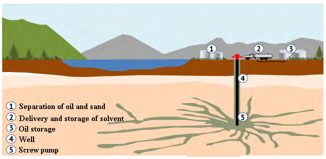
CHOPS is the least energy- and labor-intensive method among all technologies of the development of oil heavy fields with a satisfactory oil recovery rate of 10-20 %. Environmental impact is significantly lower than that of quarrying methods. There is no need for heat inherent in in- situ methods; the depth of the deposit bedding can reach more than 800 meters, less rigid requirements for the reservoir capacity as compared with in-situ methods. The main obstacle for the implementation of the CHOPS technology is rigid requirements for the collector characteristics and its hydrocarbons: - the production is possible only from the deposits of clean, non-consolidated sandstones; - oil viscosity should not exceed 10000 mPa▪s; too low or too high gas factor prevents production; -the limitation of bottom water inflow is necessary. Moreover, the issue of utilization of large quantities of sand remaining after the oil refining is a pressing concern. The industrial application of the CHOPS technology is available only in some fields of Canada. 12 million tons of heavy oil was produced with this method in 2017 [25].
Decision of Task
The Application of Thermolift in Oil Recovery Technologies
Extension of the flowing period of oil wells operation is carried out as follows: a) In depleted fields; b) In the significant reduction in the reservoir pressure; c) By increasing the gas factor; d) By reducing the weight of pole.
This increase in the flowing period activity is carried out with two methods, as it follows: a) By injecting gas into the well from the surface (gas lift method); b) By heating the oil and, in connection with this, the evaporation of light fractions directly in the wellbore (thermolift method).
There are following options for oil heating in the wellbore: a) Local (in the well bottom); b) Cascade at several points; c) In some sites.
Then, there is the direct excitation of the oil wells using the thermolift method, and here the following developments can be noted [26, 27].
Where, the possibility of raising the liquid through the well only due to the thermal expansion of the liquid is considered. It is indicated that heat transfer to the rocks surrounding the well decreases and the depth-average temperature of the liquid increases. As a result, the well flowing period is extended [26].
In the reports of Alizade MN, et al. [27] and others shown that under mentioned phenomenas are excluded. a) heat transfer by the fluid flow moving from the bottom of the well to the heating zone; b) energy loss, for the sliding of the gas relative to the moving liquid; c) hydraulic losses; d) heat exchange between the moving fluid and the rocks surrounding the well.
The indicative estimates of the thermolift appear in the following work: Alizade MN, et al. [27] and others. The study of a new method of oil recovery with the use of a thermolift for the content below:
A. estimates are given for a well with a diameter of 168 mm; Hoist diameter - 76 mm; Reservoir productivity coefficient- 3 t/d*MPa; Permissible heaviness- 5 kg/cm2; Geothermal gradient- 0.0325 grad/m. B. As a result, it has been established that: In order to lift the liquid from a depth of 1300-2000 m, 50% less electricity is required as compared to its consumption when using the compressor method of oil recovery.
Flowing Conditions for Thermolift
a) Oil heating temperature at which gas is released in sufficient quantities for the well flowing, is determined with availability of low-boiling components, i.e. oil contents. This is the main problem to be solved which is the basis for technology development; b) When calculating the vapor volume released from oil, one should take into consideration the following factors: i. the change in the physical parameters during the lifting; ii. this determines the impact on liquid and steam phases balance; iii. power of heat sources; iv. Which means the temperature along the wellbore.
Thus, the solution of this problem (with some approximations) depends on the following factors: a) location and operating mode of heating sources; b) thermal losses determined by the term and heat regime of the well operation; c) thermal resistance of tube spaces (operation method and well design); d) petroleum composition.
Let’s consider the example of thermolift estimates for a conventional gas condensate field. The estimates include the following consequence: a. Hoist calculation, i.e. determination of the required volume of the gas phase;
b. Oil temperature estimation at which the required vapor quantity of low-boiling components is provided; c. Determination of energy consumption for oil heating (taking into account the various kinds of losses) and estimation of an electric heater.
Calculation of the lifting hoist is carried out (calculated using the method by Muravyov IM, et al. [28]) with the following source data: i. well depth – 1320 m; ii. reservoir pressure – 50 kg/cm2; iii. productivity coefficient – C = 0.8 t/day*MPa; iv. degree indicator – n=1; v. permissible heaviness - ΔР= 12 kg/cm²; vi. well diameter – F = 168 mm; vii. specific oil gravity - ɣ = 0.9 kg/m³; viii. natural gas factor – V = 30 m³/t;
ix. solubility coefficient – 0.05 m³/t*MPa; x. working pressure – P – 27.5 kg/cm²; xi. absolute mouth pressure – P = 1.2 kg/cm²;
It is assumed that there is no water in the well products; The specific flow rate of the injected gas considering its solubility is calculated to be 125 m³/t; Heating temperature has been calculated with the method of consistent approximation; - Vapor temperature has been adjusted and their volume corresponding to this temperature has been compared with the required volume obtained as a result of calculation of the lifting hoist; - Vapor volume generated by oil heating in the well (when using single evaporation it has been determined with the methodology of the Ukrainian Scientific-Research Institute for Oil Industry); The calculation results are specified in (Table 1).
| Mixture components | Molecular weight | Content, % weight | Usage, kg/hour | Usage, mol/hour | Mole content | Equilibrium constant | Vapor using, kg/hour | Specific volume, m3/kg | Vapor consumption volume, m3/hour | Volumetric flow rate at T=1000 m’/hour | Specific usage m3/tone | Heat vaporization rate, cal/kg | Evaporation energy calculate kW |
|---|---|---|---|---|---|---|---|---|---|---|---|---|---|
| CH 4 | 16 | 2 | 80 | 5.0 | 11.95 | 24 | 75.5 | 1.4 | 105.8 | - | - | 0 | 0 |
| C H 2 6 | 30 | 4 | 160 | 5.33 | 12.80 | 6.0 | 130.0 | 0.74 | 96.2 | - | - | 0 | 0 |
| C H 3 8 | 44 | 7 | 280 | 6.37 | 15.25 | 2.4 | 177.5 | 0.5 | 88.8 | - | - | 0 | 0 |
| C H 4 10 | 58 | 7 | 280 | 4.83 | 11.55 | 1.4 | 141.0 | 0.37 | 52.2 | - | - | 60 | 9.8 |
| CSH 12 | 72 | 5 | 200 | 2.78 | 6.65 | 0.6 | 60.5 | 0.29 | 17.5 | - | - | 70 | 4.9 |
| C6H14 | 86 | 10 | 400 | 4.65 | 11.10 | 0.26 | 63.2 | 0.25 | 15.8 | - | - | 74 | 5.4 |
| C H 7 16 | 100 | 7 | 280 | 2.80 | 6.70 | 0.12 | 22.3 | 0.22 | 4.9 | - | - | 80 | 2.1 |
| C H 8 18 | 114 | 7 | 280 | 2.45 | 5.90 | 0.06 | 11.6 | 0.2 | 2.3 | - | - | 80 | 1.0 |
| C H 9 20 etc. | 270 | 51 | 2040 | 7.57 | 18.10 | 0.03 | 43.2 | 0.15 | 6.5 | - | - | 80 | 4.0 |
| Total | 100 | 4000 | 41.78 | 724.8 | 390.0 | 533 | 133 | - | 27.2 |
According to this table the following conclusions were reached: When oil is heated up to 100 ͦС, an average vapor output is calculated to be 133 m³/t (533m³/h). According to these calculations, oil lifting is achieved with a gas quantity of 125 m3/t. Taken temperature of oil heating of 100 °C can be considered acceptable within the accuracy of the performed calculations. Formalization of the performed calculations.
Energy consumed for oil lifting with the method of thermolift, shall be used for: a. oil and vapor heating Q;
b. evaporation of the part of oil Q; c. thermal losses in the rocks surrounding the well Q.
Then: Q = Q + Q + Q, (1) Energy calculations for oil heating is determined with a formula (watts) Q = G*c (t – t), (2) where с=2095 j/kg; °C – heat capacity of oil; t – oil temperature at a depth of 1300 m, conventionally accepted equal to natural temperature of rocks at this depth (48 ͦС) with formula (2) Q = 120 KW.
Evaporation energy consumption has been calculated for each component separately, and then summed up. Heat consumption for evaporation (in watts) of a component is determined with a formula Q = r*G, (3) where r- latent heat of vaporization in j/kg; G -vapor quantity of a component Total heat consumption for evaporation amounts to 27.2 kW. Thermal losses are caused by a process of non-stationary heat exchange between the well-filling medium and rocks, they are calculated with the following methods [29]:
Q = F*k (t – t), (4)
where k- coefficient of non-stationary heat exchange; A- surface of the well walls The following data sets are used to determine the coefficient of non-stationary heat exchange: а = 0.0039 m²/s; L = 2.35 kcal/m h ͦС; а = 180 kcal/m² h ͦ С.
Realization and Results
Electrochemical battery with solid oxide electrolyte. Device for energy production and storage with solid oxide electrolyte.
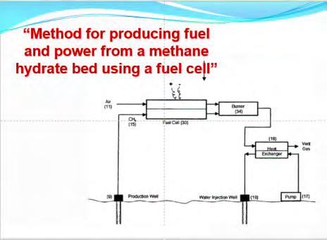
The device relates to fuel and power engineering and can be used for clean energy production, consumption and storage in various technological structures with energy and fuel systems. It is known that electrochemical device for the electrical energy production with solid oxide electrolyte [30]. This device is configured based on a module and therefore, it is possible to design them in stocks with a wide range of operational characteristics (Figure 12).
The disadvantage of these power plants is that they require fuel and oxidation systems; therefore, the material design of their electrode system does not allow performing the energy storage functions by recharging for a long time during the life cycle of operation.
One more disadvantage of these devices is that the metric characteristics of their electrode system is inconsistent with material provision and set without taking into account the process intensity on the anode and cathode surfaces accompanying energy production process.
The closest to the proposed device for energy production and storage is a device [31] presented in the form of electrode system with liquid electrolyte. This generator excludes the use of fuel and oxidation systems and allows both producing and solving the issue, as well as the storage of the produced energy. However, this device with necessary functional opportunities to produce and store the produced energy and the advantage as the use with other alternative energy sources have a number of important shortcomings which are summarized as follows: I. Firstly, the devices on liquid electrolytes are highly volatile and have a potential to catch fire during the operational process;
II. Secondly, metric dimensions of these devices are greater than those of solid oxide electrolytes and, therefore, they are not competitive in terms of commercial performance and are more expensive due to lack of opportunities of intercomparison of metric normals of electrodes and volume of electrolyte contents;
III. Thirdly, these devices are less effective as compared to those with solid electrolytes and inferior to them on indicators of quality (shorter service life), etc.
The object of the device is to develop safe, small-sized, cheap and improved performance and quality indicators for the service cycle of electrochemical generators with the corresponding operational properties, metric characteristics for the production, distribution and storage of clean energy. The assigned task is solved by the fact that a compatible combination of destination phenomena, implementation form, material performance, metric characteristics of the electrode system, design and operating parameters of fuel supply systems, including its type and oxidizer, as well as operational thermobaric accompaniment, is used as the design data for making devices with adjusted performance levels and service cycle duration in the general device architecture.
The device scheme is shown in (Figure 13) [31], including the above listed subsystems where 1- solid oxide fuel cell, 2- gas- turbine equipment, 3- fuel system, 4,5,6- accordingly, supply and discharge lines for air, fuel and combustion products, 7- generator, 8- electricity network, 9 - …., 10 - …. etc.
Depending on its structural design including the form and characteristics of material provision and the mode- technological requirements imposed on it, a configuration of the whole device is formed [30].
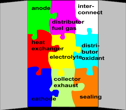
Each combination of solid oxide structure with a different form of performance and the corresponding material design calculated for certain generated powers is designed with the necessary metric indicators of the structure and the physico-mechanical characteristics of its material provision. The device formed in the form of a puzzle (Figure 14) of subsystems that complement its configuration, works as follows.
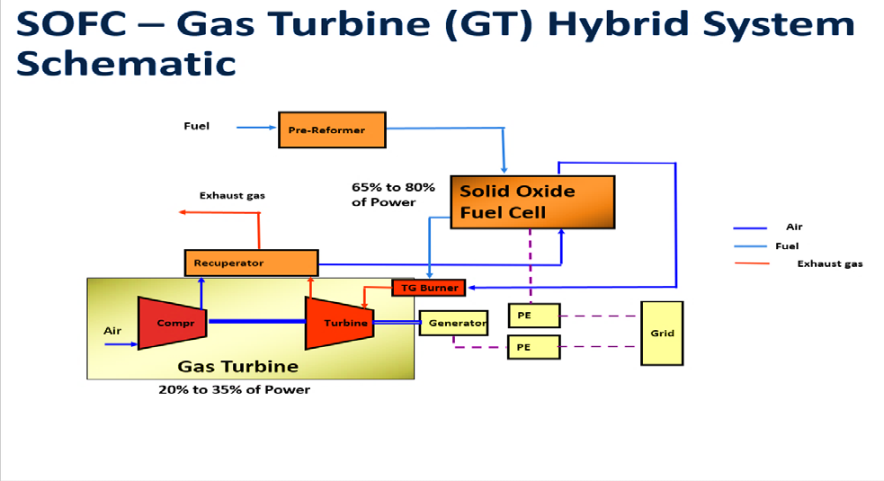
The main element is the power generation system including TOTE of solid oxide structure with the various design form that exposed to high operating temperature and other energy equipment combined from gas and/or steam turbine generators (Figure 15) [30].
The specification for the power indicators of the device generating system considers such indicators as efficiency, price characteristics (both purchase and installation), reliability, cycle obligation, maintainability, dimensions and weight, the list of fuels used, etc. (for instance, generation repetition, noise characteristics, quality of the produced energy) (Figure 16)[31].
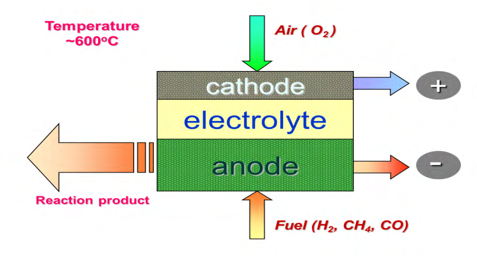
The device operates as follows. It is supplied through the fuel and oxidizer supply systems to the working surfaces of the anode and cathode electrodes, accordingly, fuel and oxidizer. Due to chemical reactions on these surfaces, the fuel and oxidizer are ionized with the release of a high temperature which results in the appearance of high thermal stresses. The released free electrons, as a result of chemical reactions on the electrode surfaces, form an insular electric circuit with a corresponding electromotive force. Being filtered through a porous solid oxide electrolyte with certain metric characteristics and physical and mechanical properties, ions form by-products in the form of hot water and exhaust gases.
The above mentioned characteristics and properties determine the specification of the power indicators for the generating device system, i.e. electrode system, consider such indicators as efficiency, price characteristics (both purchase and installation), reliability, cycle obligation, maintainability, dimensions and weight, the list of fuels used, etc. (for instance, generation repetition, noise characteristics, quality of the produced energy) [30].
Conclusion
Studies on a specially equipped stand, numerical simulations of the obtained analytical solutions showed that the most rational characteristics and properties of the electrode system for generating the power of the device, depending on the form of design, are the data shown in (Figure 17).
It has been established that the best metric characteristics with acceptable thermo-physical properties of the electrode system materials, power of the generating device can be determined with graphs shown in (Figure 18 &19) [31].
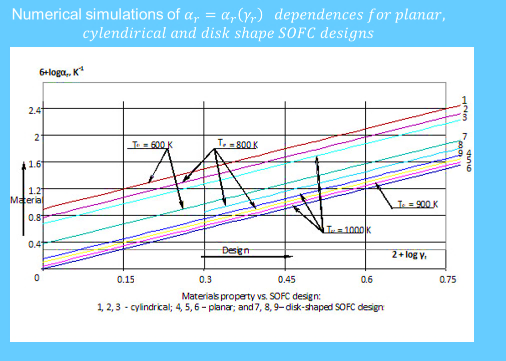
Figure18: The best thermo-physical properties of the materials depending on operating temperature.
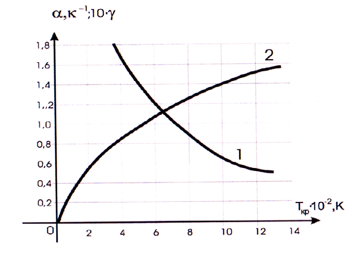
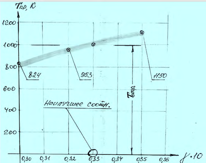
Figure 19: Dependability of the metric characteristics on operating temperature. Thus, pursuant to own studies for the operating temperature accompanying the electrode systems of solid oxide power generating devices equal to 1000 °C, its acceptable metric characteristics have been determined (by the ratio of the thickness to one of the transverse dimensions) 10ƴ(δ/М)= 0.34, as well as the averaged thermo-physical property for this operating temperature equal to α= 1.2 к-1. These properties and metric characteristics provide the device effectiveness for the period of the established service life without technological risks and complications.
The results of the studies were included in projects dedicated to the development and implementation of low (SFP No. G5366 dated 09.02.2017) and high temperature fuel cells (EAPSFP 984580- 01.01.2005- 01.01.2009) and funded by NATO under the Science for Peace program and reported at the session of the Advanced science institute (ASI – Advanced science institute -16.04.2012) NATO, fulfilled in a consortium with specialists from the USA, Great Britain, Turkey, Russia, Ukraine, Belarus [30].
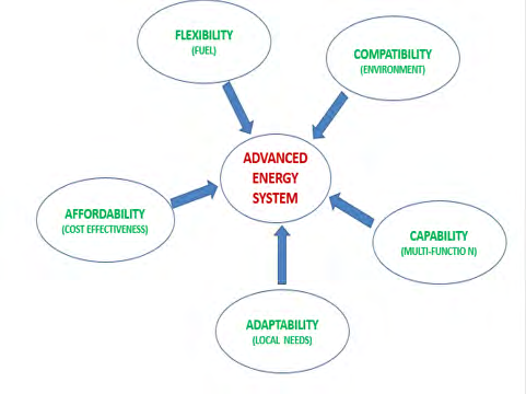
A series of requirements are placed on modern electric power systems that determine the prospects of their application in various industries, including oil and gas fields. These requirements are aimed at improving the consumer quality (Figure 20) of the applied systems and are mainly reduced to the degree of their commercialization (1.determines availability), a lot of functionality (2.determines ability), loyalty to the environment (3.determines interaction with the environment), compliance with the conditions of the location of operation (4.determines the requirements of the location), readiness and availability in terms of the quality and volume of fuel consumed (5.determines the flexibility in the use of fuel). This is due to the fact that the level of global energy consumption and, accordingly, a decrease in the negative and harmful impact of production processes implemented for this purpose on the environment is increasing rapidly.
Presently, taking into consideration the potential opportunities and perspectives for the devices application as an alternative and resource-saving source on the production of green energy, there is an active search for implementation of the achieved results in the national projects of various uses and implementation form, including opportunities to apply it in the power supply of the de-annexed Karabakh territories of the Republic.
References
-
Santos RG, Loh W, Bannwart AC, Trevisan OV (2014) An Overview of Heavy Oil Properties and its Recovery and Transportation Methods. Brazilian Journal of Chemical Engineering 31(3):571-590.
-
Williams В (2003) Heavy hydrocarbons playing key role in peak-oil debate, future energy supply. Oil & Gas J.
-
Asaulov S Non-conventional sources of hydrocarbons: shale bubble or shale revolution? ROGTEC magazine.
-
Grushevenko D, Grushevenko Y (2012) Shale oil-a new challenge to the global energy market? М.: INEI RAN.
-
Natural Resources Canada Exploration and Production of Shale and Tight Resources, Natural Resources Canada.
-
Proceedings of the Twelfth World Petroleum Congress, Houston, TX, USA.
-
Unconventional oil.
-
USGS (2003) Heavy Oil and Natural Bitumen-Strategic Petroleum Resources. United States Geological Survey.
-
EIA (2021) U.S. Energy Information Administration, World Shale Resource Assessments.
-
Petrodigest, heavy-crude-oil.
-
About the Classification of Heavy High-Viscosity Oils.
-
Shchepalov-alternativnye istochniki.
-
Georgie W, Smithhttps C (2012) The Challenges in Processing Heavy Oil. The SPE Heavy Oil Conference Canada, Calgary, Alberta, Canada.
-
Mingareyev RSh, Tuchkov II (1980) Operation of bitumen and oil shale fields. M Nedra, pp: 572.
-
Konoplev YP, Tyunkin BA, Grutskiy LG, Pitirimov VV (2002) Yaregskoye field - 70 years of discovery and 30 years of thermal-mining development. Oil industry 12: 59-60.
-
Surface Mining Techniques used in the Oil Sands. Oil sands magazine.
-
U.S. Department of Energy (2008) Annual Report to Congress on Strategic Unconventional Fuels Activities and Accomplishments. Assistant Secretary for Fossil Energy Office of Petroleum Reserves U.S., Department of Energy Washington, DC 20585.
-
Dembicki E (2007) An overview of Albetra Oil Sands and Recovery Technologies. XVIII Latin American Petroleum Show, Maracaibo, Venezuela.
-
Baybakov NK, Garushev AR (1989) Thermal methods for the development of oil fields. Nedra, pp: 343.
-
Bottom-hole zone, Mining encyclopedia.
-
Oil sands magazine. Thermal In-Situ Facilities.
-
Kudinov VI (1996) Improvement of thermal methods for the development of highly viscous oil fields. M Oil and Gas, pp: 284.
-
SPE (2021) Encyclopedia of the Community of Petroleum Engineers. Society Petroleum Engineering.
-
Abishev A, Tokarev V, Sagyndikov M (2018) Evaluation of In-Situ Combustion Efficiency in Karazhanbas Oilfield, Western Kazakhstan. The SPE Annual Caspian Technical Conference and Exhibition, Astana, Kazakhstan.
-
Canadian Heavy Oil Association. Recovery Process - Cold Heavy Oil.
-
Chekalyuk EB (1965) Thermodynamics of an oil reservoir. Nedra Publishing House.
-
Alizade MN (1959) To the study of a new method of oil recovery with the use of a thermolift. Reports of the Academy of Sciences of the AzSSR 15(2).
-
Muravyov IM, Kpylov AP (1949) Operation of oil fields. Gostoptekhizdat.
-
Shcherban AN, Kremnev OA (1959) Scientific basis for calculating and regulating the thermal regime of deep mines. Vol 1, Publishing House of the Academy of Sciences of the Ukrainian SSR.
-
Abdalla AM, Hossain S, Petra PM, Ghasemi M, Azad AK (2020) Achievements and trends of Solid Oxide Fuel Cells in clean energy field: perspective review. Front Energy 14(2): 359-382.
-
Hasanov RA, Gulgazli AS, Kazimov MI, Musevi SA (2012) Investigations of mechanical problems of SOFC development and applying processes. Science for Peace Program of Nato, Session of Advanced Study Institute (ASI). Kiyev, pp: 131.
- Nigeria’s Vulnerability in the Face of Global Energy Policy
- A Simulation Study of Investigation of Optimum Oil Production Performance by Applying Various Gas Injection Methods in Oil Reservoir
- Characterization of Permo-Triassic Reservoirs through Thermal Maturity Assessment of Westphalian Source Rocks in the Cheshire Basin
- Influence of Microwax on the Rheological and Thermal Behaviour of a Wax Crude Oil
- Real-Time Monitoring and Performance Optimization of Steam Injection in Heavy Oil Reservoirs Using Fiber Optic Sensing and Integrated Predictive Simulation Models
- Rapid On-Site Determination of the Total Petroleum Hydrocarbon Content of Soils by Handheld Fourier Transform Near-Infrared Spectroscopy: Development of a Global, Site- and Scanner- Independent Calibration Model