Constructing a Heavy Oil Well
The article presents a description of the designs of wells intended for the production of high-viscosity oil. The main problems associated with the planning and deployments of architecture, construction of high-viscosity oil wells are described. World experience in well construction is presented. Vertical wells are usually used for primary cold production and cyclic steam or steam flooding processes. On the other hand, increased reservoir contact may require deviated, horizontal, or multilateral wells. In the case of steam-assisted gravity drainage (SAGD) and some solvent injection processes, the recovery process may require a well-placed pair of horizontal wells. Advanced drilling and real-time measurement technologies reviewed. Geo mechanical factors are studied when considering the implementation of any steam or thermal processes in the field. Examples of construction of multilateral wells in various combinations are shown depending on the field development strategy and for maximum reservoir drainage. The main recommendations for the placement of wells are proposed.
Introduction
The common practices for heavy oil well architecture and completions depend on the type of recovery methods deployed to exploit heavy oils and bitumen. Vertical wells are usually used for primary cold production and cyclic steam or steam flooding processes. On the other hand, increased reservoir contact may require deviated, horizontal, or multilateral wells. In the case of steam-assisted gravity drainage (SAGD) and some solvent injection processes, the recovery process may require a well-placed pair of horizontal wells. Let us review the challenges associated with planning and deploying well architecture, construction, and completions in the following section.
There are numerous challenges associated with well planning, architecture, placement, and completions that, to a large extent, depend on the planned production process or sequence of production processes to be used to recover the heavy oil. Some of the key challenges are as follows:
- Most heavy oil reservoirs are located in shallow and unconsolidated formations. In this environment, the foremost challenge is maintaining wellbore stability after the borehole is created but before casing is placed.
- Another critical aspect of well completion for these shallow unconsolidated heavy oil formations is implementation of a suitable sand management strategy.
- For applications that require a pair of horizontal wells, proper planning and placement pose significant challenges in terms of maintaining a constant distance between the two wells.
- The injection of steam and recovery of hot heavy oil associated with steam processes necessitates exposure of all of the components in the wellbore to high temperatures (from 150°C to 280°C for SAGD) for a long period of time. The sustained high temperatures present a particular challenge in maintaining the integrity of wellbore tubulars and elastomers used in the progressive cavity pumps. Failure of both the wellbore tubulars and pump elastomers can cause significant operational issues related to steam leaks through the annulus, exposing the casing’s wellbore tubulars and pumps to a corrosive environment.
- The highly viscous nature of the heavy oil, particularly in cold production scenarios, requires serious considerations when selecting and deploying a suitable lifting mechanism.
Materials and Methods
The construction process for vertical wells for heavy oil applications is similar, in most aspects, to the processes used in the construction of vertical wells for unconsolidated conventional oil formations. Differences arise when the planned production process involves mobilizing the heavy oil by heating, typically with steam. The key difference is the potential exposure of the casing and well tubulars to high temperatures and large fluctuations in temperature during startup and shut down operations. Specialized high- temperature resistive tubular should be considered from the planning phase and deployed accordingly.
In the case of SAGD, two parallel horizontal wells are drilled on top of each other, usually 5-6 m apart. The top well is an injection well while the bottom well is a production well. In the past, when real-time drilling measurement techniques were less developed, the placement of two parallel wells posed significant complications. However, with the advancement of reliable ranging tools and a good understanding of geological heavy oil pay zone as a priori, drilling engineers are now able to place two parallel wells in close proximity more accurately. The advanced real-time drilling and measurement technologies are also enabling drillers to avoid exiting the oil-bearing pay zone during the drilling process. As a consequence, drillers minimize the number of corrections to the drill angle required to reenter the pay zone and, in turn, reduce the nonproductive time (NPT) during drilling. These advanced real-time drilling and measurement technologies and established step-by-step procedures are enabling engineers to optimize SAGD processes, and hence, maximize the recovery.
In 2005, Mottahedeh R proposed and applied the following recommendations for well placement [1]:
- Utilize advanced drilling technologies like directional drilling, measurement-while-drilling (MWD), logging- while-drilling (LWD), and so on.
- Deploy the technologies that enable capture and transmittal of real-time data during drilling and also software technologies that convert real-time data into information.
- Finally, ensure strong interaction and coordination of team members.
Successful and accurate well placement requires the team of geoscientists, drilling engineers, and drilling operators to make correct and timely collective decisions.
In addition to the recommendations stated above, Mottahedeh also described the basic step-by-step process for a successful well placement [1]:
- Clearly define the oil-bearing pay zone target and the expected well trajectory beforehand.
- Obtain and collectively monitor reservoir information as the drilling operation progresses.
- Compare the real-time drilling data with the target well trajectory and make adjustments to the drill plan immediately.
If there are any expected deviations in rock properties, take immediate corrective measures to avoid getting out of the hydrocarbon-bearing zone.
It is a major undertaking for the drilling engineers to place the horizontal section fully within the pay zone for maximum reservoir contact. Prior to the start of drilling operations, engineers will prepare a well trajectory using the initial subsurface geological model. This subsurface model is usually an approximation because of the uncertainties associated with the initial seismic and geological interpretations. Any deviation in drilling from the productive zone into the overburden or under burden will result in a more complex drilling operation because of the need to reenter into the zone of interest. Deviation from the drill plan will cause delays, adding the cost of NPT to the overall cost of drilling. The original wellbore is sometimes abandoned due to drilling complexities and a separate wellbore starting within the zone of interest is drilled. This is called “sidetracking.” Drilling engineers must also ensure that the horizontal section is not placed too close to the bottom of the reservoir. If the reservoir is underlain by an active aquifer, penetration through the bottom of the reservoir could lead to early excessive water production. To avoid significant deviations from the drilling plan, engineers correct the well trajectory and appropriately place the well in the productive zone using the real-time geological information gathered during the drilling operations [2]. This real-time decision- making during the drilling operation, especially for the horizontal section, is critical to achieving a successful and productive wellbore.
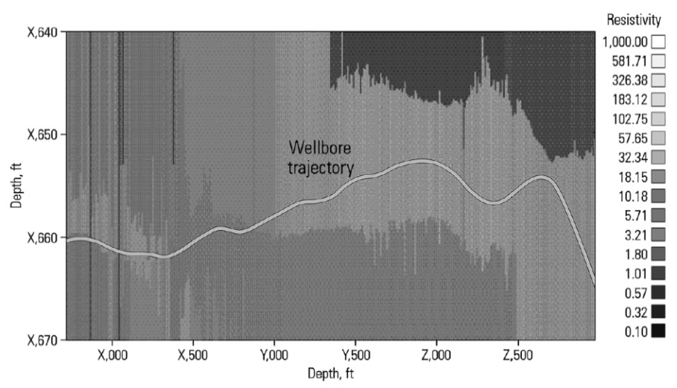
Meehan defines “geosteering” as the geological steering of horizontal wells [3]. The process of geosteering is basically incorporating the information, as it is obtained, from LWD technology into the well trajectory plan and then making any necessary directional corrections in real time to maintain the well in the zone of interest. This practice has enabled drilling engineers to make significant advancement in placing the well in the appropriate pay zone.
Figure 1, reproduced from Chou, et al. illustrates an example of a geosteered well using resistivity response from the LWD technology [4]. In this example, the zone of interest is illustrated using a light gray color. The geosteering team was able to change the direction of the well using the resistivity response from the LWD tool. As seen in the figure, a change in the direction of the well path is identified at a distance of X, 500 feet and a major correction in the direction of the well is made at Z, 500 feet.
The term “proactive geosteering” is used by Seydoux, et al. [5]. This concept is simply the early recognition of the upcoming reservoir tops and bottoms as well as the oil-water contact regions and making minor corrections to drilling angles in real time. The early recognition is made possible by the availability of LWD information. The ability to recognize the need for minor corrections early is critical for maintaining the well within the pay zone, and hence, avoiding a severe deviation in the drilling angle. Proactive geosteering enables drilling engineers to create a productive horizontal section.
Heavy oil accumulations are usually found in high- permeability, high-porosity, and well-defined pay sections. Regardless of the pay quality, it is important to have an appropriate horizontal completion design and strategy for commercial success. Once SAGD has been selected as an optimal candidate for a heavy oil reservoir, operators will drill many pairs of horizontal wells from the same surface location. These horizontal well pairs are commonly 1,400- 1,600 m (4,600-5,200 ft.) long with horizontal sections of 800-1,200 m (2,600-3,900 ft.) placed within the pay zone. Normally, when there is no active bottom water layer, the production well is placed at the bottom, close to the under burden. The injection well is placed roughly 5-6 m above the production well. The distance between the production and the injection wells influences the recovery factor and the efficiency of the SAGD process. If the wells are drilled too close to each other, there will be early breakthrough of steam around the heel, resulting in an inefficient steam process with a low recovery factor. Similarly, if the distance between the two wells is too large, then it will take a long time, sometime several months, to establish hot communication between the injection and production wells. Hot communication means the heavy oil between and surrounding the well pair has heated sufficiently to reduce its viscosity to the point where the oil is mobile and can be produced. Therefore, careful consideration is required to optimize the distance between the two horizontal wells for SAGD application.
While drilling a pair of SAGD wells, first a production well is drilled, cased, and cemented at the bottom of the pay section using advanced drilling technologies like MWD. “Magnetic ranging” technology is then used to drill the parallel injection well [6]. This technology uses a source magnet in the already drilled production well. The source magnet is usually deployed using either coiled tubing or a wire line tractor in the production well. The MWD tool then uses the responses from the source magnet placed in the production well and adjusts drilling direction to maintain a preplanned distance between them. Drilling a parallel injection well using the MWD tool with magnetic ranging will require simultaneous access to the production well.
Rennie, et al. also describes an alternate concept where a pre-magnetized casing is used instead of a source magnet in the production well as a passive magnetic source [6]. Consequently, a parallel injection well can then be drilled, maintaining quite an accurate preplanned distance using MWD responses. The primary advantage of this alternative approach is that the parallel injection well is drilled without having to access the production well.
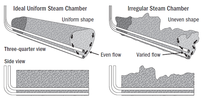
For an optimum SAGD process, it is necessary to have a uniform steam chamber and allow an early communication with the production well so that heated oil can drain easily. Figure 2 graphically compares ideal and real (irregular) steam chamber growth. As seen in the figure and as discussed by Akram, et al. the ideal steam chamber is far from reality [7]. The chamber grows irregularly because of various factors (such as reservoir heterogeneity and irregularity in the well path) that combine to result in a less efficient SAGD process and a lower than ideal recovery factor.
Some of these factors, like heterogeneity, are not under the control of the operating company. However, factors like choosing the right candidate reservoir, placing the well in a pay section with more geological homogeneity, and proper well trajectory can make the SAGD process more efficient and can allow the operating company to achieve greater economic success. Thus, candidate reservoir selection and proper well planning are important for technical as well as economic success of the project.
Results
Geomechanics and Steam Injection
Collins, et al. have shown that the steam processes not only impact the wellbore integrity because of elevated temperature and pressure conditions, but also increase pore pressures in the formation [8]. This increased pore pressure condition then reduces the effective stress on the overburden or caprock. In addition, the elevated temperature also allows the steam chamber to expand. Since area surrounding the steam chamber is colder, the steam chamber expansion forces the overburden to move upward. This upward movement of the overburden creates shear fractures above the injection well and causes steam to escape. Therefore, overburden or caprock integrity is a major concern for reservoir engineers.
Over the years, engineers have studied and developed geomechanical workflows to proactively understand changes in rock properties caused by the elevated reservoir temperatures associated with steam injection [9]. They build geomechanical models using field measurements like reservoir pressures, sonic responses, and laboratory analyses of rock samples. Using the workflows and thermal simulations, engineers then evaluate various steam injection scenarios and predict variations in temperature and pressure conditions. These variations in temperature and pressure conditions and the geomechanical models enable operators to predict the potential for caprock failure, including the potential failure location. Hence, it is critical to have a thorough understanding of geomechanical factors when considering implementing any steam or thermal processes in the field.
Multilaterals
Multilateral wells are simply the multiple short or long horizontal sections of boreholes drilled from a single wellbore. The primary objective of these derivative horizontal boreholes is to achieve maximum reservoir contact from one surface access, reducing cost and maximizing recovery. Fraija, et al. has provided a comprehensive summary of multilateral technologies, their advancements and applications. [10]. Besides their applications in conventional reservoirs, multilaterals are most suited for heavy oil exploitation because of their maximum reservoir contacts, which enable draining high-viscosity heavy oils.
From a completions perspective, the use of multilaterals allows operating companies to take advantage of single- surface access. Single-surface access typically requires less infrastructure, and hence, potentially reduces overall field development investment. Figure 3 illustrates a few example configurations of multilateral wells. As shown in the figure, multilaterals can be a combination of horizontal sections configured in a fan shape, stacked on top of each other, or two horizontal sections directly opposite to each other stemming from one wellbore drilled from the surface [10].
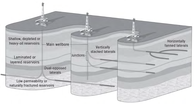
Depending on the field exploitation strategy and to maximize the reservoir drainage, multilateral completions are used in various combinations. All laterals are then connected to the main wellbore that extends to the surface. A detailed reservoir engineering evaluation is required to evaluate the optimum use of multilaterals for exploiting the heavy oil field. During the evaluation, engineers attempt to find the optimal solution by assessing several parameters; include the profile, length and placement of laterals, type of connections to the main wellbore, and the location of the main wellbore connecting to the surface.
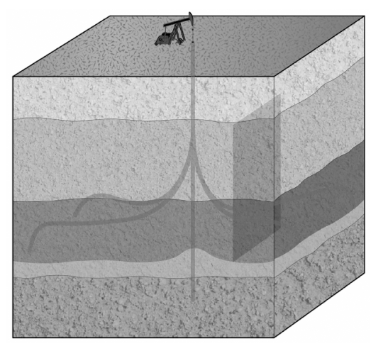
The challenge of well positioning, which is critical in SAGD and similar dual-well operations, can be addressed by geosteering technologies. Planning is the key to successful completion of the drilled wells. A primary example of detailed planning requirements is the use of multilateral wells in heavy oil production. Completion planners for multilaterals have benefited from the development of technologies that allow for Fraija, et al. deduce from field observations for CSS and steam flood operations that the horizontal extensions of these lateral sections (Figure 4) usually have better steam efficiency and better ultimate maximum heavy oil recovery [10]. The proximity of the multilateral wells makes the reservoir warmer, meaning that it requires less heating of steam compared to more conventional well construction. The other advantage of the horizontal laterals is that they prevent early water or gas coning in thin formation.
interventions with minimal disruption to production. Much of this technology development is captured by the various completions categories, including TAML classifications. Finally, the installation of intelligent completions, particularly reservoir monitoring, are important sources of data for operation engineers and operators looking to monitor and control heavy oil production processes. Intelligent
completions allow operators to monitor the development of the steam chamber along the length of the SAGD well pair or to manage flow in the wellbore in order to control water or steam breakthrough.
References
-
Mottahedeh R (2005) Horizontal Well Geo-Navigation: Planning, Monitoring, and Geosteering. 6th Annual Canadian International Petroleum Conference, Calgary, Alberta.
-
Chemali R, Bittar M, Hveding F, Wu M, Dautel M (2010) Improved Geosteering by Integrating in Real Time Images from Multiple Depths of Investigation and Inversion of Azimuthal Resistivity Signals. SPE Res Eval Eng 13(02): 172-178.
-
Strelets LA, Ilyin SO (2021) Effect of enhanced oil recovery on the composition and rheological properties of heavy crude oil. Journal of Petroleum Science and Engineering 203: 108641.
-
Chou L, Li Q, Darquin A, Denichou JM, Griffiths R, Hart N, et al. (2005) Steering toward Enhanced Production. Oilfield Review 17(3): 54-63.
-
Seydoux J, Tabanou J, de Laet Y, Omeragic D, Denichou J, et al. (2004) A Deep Resistivity Logging-while-Drilling Device for Proactive Geosteering. The Leading Edge 23(6): 581-586.
-
Rennie A, McElhinney G, Illfelder H, Ceh L, Schaepsmeyer H, et al. (2008) A Case Study of a New Technique for Drilling SAGD Twin Wells in Heavy Oil Reservoirs. World Heavy Oil Congress (WHOC), Edmonton, Alberta.
-
Akram F, Stone T, Bailey WJ, Forbes E, Freeman MA, et al. (2014) Warming to Heavy Oil Prospects. Oilfield Review Summer, pp: 4-15.
-
Olkhovskaya VA, Roschin PV, Struchkov IA (2021) Heavy oil production. Publishing and Printing Association of Higher Educational Institutions, St. Petersburg, USA.
-
Khan S, Han H, Ansari S, Khosravi N (2011) Geomechanical Modeling to Assess Caprock Integrity in Oil Sands. Canadian Society of Petroleum Geologists, the Canadian Society of Exploration Geologists, Canadian Well Logging Society Annual Convention, Calgary, Alberta.
-
Morozov PE (2020) Analytical Solutions for Transient Temperature Distribution in Heavy-Oil Reservoir due to Heating Producer Well. Lobachevskii Journal of Mathematics 41(7): 1261-1266.
- Nigeria’s Vulnerability in the Face of Global Energy Policy
- A Simulation Study of Investigation of Optimum Oil Production Performance by Applying Various Gas Injection Methods in Oil Reservoir
- Characterization of Permo-Triassic Reservoirs through Thermal Maturity Assessment of Westphalian Source Rocks in the Cheshire Basin
- Influence of Microwax on the Rheological and Thermal Behaviour of a Wax Crude Oil
- Real-Time Monitoring and Performance Optimization of Steam Injection in Heavy Oil Reservoirs Using Fiber Optic Sensing and Integrated Predictive Simulation Models
- Rapid On-Site Determination of the Total Petroleum Hydrocarbon Content of Soils by Handheld Fourier Transform Near-Infrared Spectroscopy: Development of a Global, Site- and Scanner- Independent Calibration Model