Cardiac Treatment and Monitoring Devices Encountered on Chest Radiography: From Radiologic Appearances to Potential Complications
Cardiac monitoring, support, and treatment devices are frequently seen on chest radiographs. As cardiac therapeutic interventions evolve, these devices grow in prevalence and diversity. New devices are introduced on a regular basis, and although knowing their specific names is not critical, it is imperative to recognize their radiologic appearances, understand their purpose, and be aware of potential complications associated with their use.
Introduction
Chest radiography is still the test of choice in many clinical situations due to its low cost, rapid acquisition and its ability to assess a wide range of emergent and chronic conditions [1]. Routine and emergent chest radiographs are required for cardiac monitoring as well as evaluation of device placement, and possible device complications such as migration of device. Cardiac devices are common and widely used in healthcare, their prompt recognition and assessment in chest radiographs is a fundamental tool for adequate patient care. The current article illustrates the radiographic appearances of commonly used cardiac medical devices, describes their purpose and important potential complications that should be promptly recognized and treated in multiple clinical scenarios. The specific magnetic resonance imaging compatibility of each device will be examined.
Different Device Categories
For this review, the cardiac devices have been subcategorized in the following sections: Cardiac pacemakers and defibrillators, cardiac valve devices, closure and repair devices, pressure assist devices and cardiac monitoring devices.
Cardiac Pacemakers and Defibrillators
Cardiac pacemakers and implantable cardioverter defibrillators (ICDs) are very commonly encountered on chest radiographs. Although these devices can be used at all ages, they are most seen in older adults. Cardiac pacemakers utilize small electrical pulses to stimulate cardiac contraction in response in patients with bradycardia or arrhythmias [2, 3]. Implantable cardiac defibrillators utilize high voltage stimuli to defibrillate the heart in case of ventricular fibrillation [2, 3]. A pacemaker or ICD consists of a generator that is implanted in the anterior chest wall, and one or more wire leads that are inserted into a vein, typically the subclavian or axillary vein, and threaded into position within the heart. The position of the leads depends on the targeted chamber for pacing. Typical locations include the right atrium, right ventricle and coronary sinus or azygous vein. ICDs are distinguishable from pacemakers by the dense shock coils on the lead wire [2]. Pacing leads and shock coils are also used in combination (Figure 1). Historically these devices were Magnetic Resonance (MR) unsafe, however new devices are being designed for MR compatibility, so many are now MR conditional, but the category is device dependent. Distinctive protocols are under development for patients whom the advantages of undergoing an MRI procedure surpass the associated risks [4].
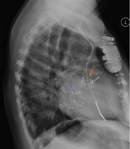
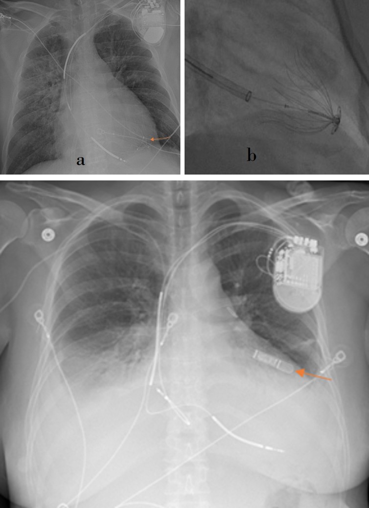
Serious complications of implanted cardiac pacemakers and defibrillators that may occur shortly after insertion include pneumothorax, hemothorax, infection, myocardial perforation, and cardiac tamponade. Their potential long- term complications include lead displacement, lead fracture damage of lead insulating coating, retraction of leads by twisting around the generator (Twiddler’s syndrome), and inappropriate shocks [2, 3, 5]. Subcutaneous ICDs are an alternative to conventional intravenous ICDs; and they are utilized when there is venous occlusion or structural heart disease. The wire leads of these devices are positioned in the subcutaneous fat planes overlying the anterior chest wall [6, 7] (Figures 2a, 2b). MRI safety is conditional depending on the device [4].
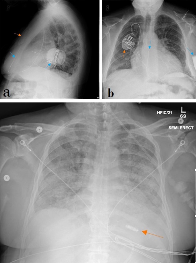
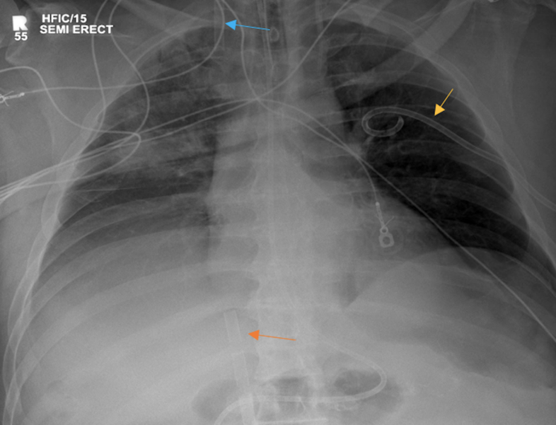
Figures 2a & 2b: Lateral (a) and PA (b) chest radiographs demonstrate right chest wall, right subclavian vein approach triple leads cardiac pacing device (orange arrow) as well as left chest wall, single pre-sternal lead AICD with lead terminates in subcutaneous tissue near the manubrium-sternal junction (blue arrows).
Leadless pacemakers have been recently introduced and as suggested by their name, they lack any wire leads. These devices are inserted by catheterization of the right heart chambers and placing the device at the right ventricular apex [8] (Figure 3a). These devices are anchored to the ventricular wall using hooks in the case of the Micra transcatheter Pacing system, and fixation screw helix in the case of the Nanostim Leadless Cardiac Pacemaker (Figure 3b). The AVEIR is a dual-chamber leadless pacemaker, which is placed in both the right atrium and right ventricle for synchrony between both chambers (Figure 3c). Dual chamber pacemakers are especially useful for sick sinus syndrome [9]. Potential complications of leadless pacemakers include dislodgement and embolization, thrombus formation, and device malfunction [8]. MRI compatibility is dependent on the specific device. Micra by Medtronic have compatibility up to 3T and a specific absorption rate (SAR) below 3.2 W/kg.
Figure 3a: AP chest radiograph shows a Micra implantable leadless pacemaker (orange arrow) projecting over the right ventricular apex, this is the correct position.
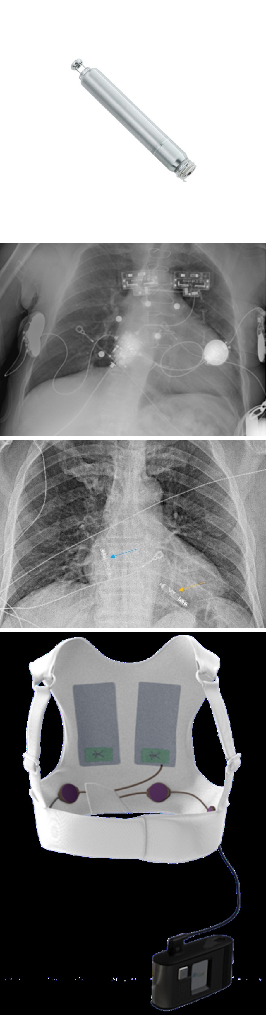
Figure 3b: Nanosmith leadless cardiac pacemaker with 1 Euro coin for size comparison. Figure 3b reprinted, with permission, Abbot.
Figure 3c: PA chest radiograph demonstrating dual chamber leadless pacemaker, with one device in the right atrium (blue arrow), and another one in the right ventricle (yellow arrow).
Wearable cardioverter-defibrillator (WCD) is an externally worn device designed to prevent sudden cardiac death by detecting arrhythmia and defibrillating ventricular fibrillation and/or ventricular tachycardia. The WCD electrodes and therapy pads lie on the skin surface and serve the same purpose as those on the shock leads of conventional ICDs. Although these devices can be worn for several years, they tend to be used as a temporary measure until an underlying medical condition has resolved or until a conventional device is implanted. WCDs are identifiable on radiography (Figures 4a,4b). WCD is not inherently compatible with MRI but can be safely removed to facilitate an MR study.
Figure 4a: Frontal PA chest radiograph depicts an external defibrillator life vest; electrodes are on the skin surface.
Figure 4b: A photo of Zoll Life Vest. Figure 4b is reprinted, with permission, from Zoll.
Temporary pacing epicardial electrodes may be placed during cardiac surgery when bradycardia occurs after termination of cardiopulmonary bypass or when bradycardia is anticipated due to surgical manipulation close to the atrioventricular (AV) node (e.g., during mitral valve replacement). These electrodes extend from the anterior surface of the heart and out through the skin. The electrodes can be plugged into an external pacemaker to stimulate ventricular contraction when needed (Figure 5). These electrodes are pulled out through the skin when they are no longer required, usually at discharge [6]. However, if these electrodes cannot be withdrawn with gentle traction they may be cut with scissors at the skin and the remaining part can be left inside the body which can be seen on subsequent imaging. No clear consensus on the MRI safety of retained pacer wires, necessitating individual assessment in each case.
Cardiac Valve Devices
Prosthetic heart valves have been used to replace diseased native valves since the 1960s with a wide host of prosthetic valves developed and regularly used [6, 10]. The valves typically consist of an anchoring annulus and an intermittent occluding mechanism, designed to simulate the function of the native valves. Biologic and mechanical cardiac valves have been developed with the biologic valves utilizing human cadaveric tissue (homograft) or animal (typically porcine or bovine xenograft tissue), whereas mechanical valves are manufactured from purely synthetic materials and metals [6, 11]. Biologic grafts have the advantage of requiring no or less anticoagulation compared to mechanical valves which require life-long anticoagulation. However, biologic valves degrade and more frequently require reintervention [6]. Most aortic, pulmonic, mitral and tricuspid valves are MRI- compatible up to 3T with a Specific Absorption Rate (SAR) of 2 w/kg. Each valve model needs verification for compatibility as some might be categorized as conditional [4].
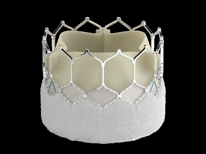
The ball-and-cage style valve is one of the earliest artificial valve designs (Figures 6a,6b), but several other designs have been developed since then (Figures 7a,7b,8a,8b,9a,9b). While the aortic and mitral valves are the most commonly replaced, all heart valves may be replaced [12] (Figures 10a,10b). Most devices are MR conditional, some models are safe up to 1.5T, other up to 3T [4]. The rapid expansion of minimally invasive cardiac interventions and development of more sophisticated equipment has allowed placement of cardiac valves through an arterial or a venous catheter. Transcatheter aortic valve replacement (TAVR) has been approved by the Food and Drug Administration (FDA) and for treatment of severe aortic stenosis. TAVR is preferred in older patients with lower performance status who have a higher risk for developing complications from conventional open heart surgery [11, 12]. TAVR prosthesis can be distinguished from surgically implanted valves by their wire-mesh appearance which expands the valve and anchors it to the aortic annulus upon exiting the catheter tubing. Two main types of TAVR mechanisms are currently available; self-expandable valves (Figure 11) and Ballon expandable valves (Figure 12). Their biggest difference is in deployment mechanism, flexibility, conformity to the native anatomy, and the characteristics of the procedure. Both have been shown to be safe and effective in treating aortic valve disease, the choice depends more on patient characteristics and physicians’ expertise. TAVR devices can be combined with other valve replacements, including transcatheter mitral valve replacement (Figures 13a,13b). TAVR prosthesis can be used to treat native aortic valves or previously placed failing prosthetic valves (valve-in-valve procedure) [11] (Figure 14). Other types of transcatheter valve replacement are available including Tendyne Transcatheter Mitral Valve Implantation and Transcatheter Pulmonic valve implantation (Figures 15a,15b). The most common complication is migration of the valve, which can be evaluated with chest radiograph (Figure 16). Most models are considered MR Conditional for 1.5T and 3T [13].
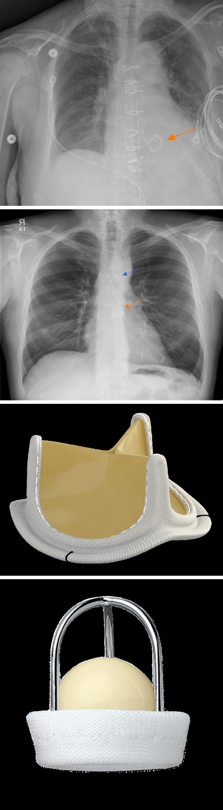
Figure 6a: PA chest radiograph showing ball in cage aortic valve replacement (orange arrow), median sternotomy wires (blue arrows).
Figure 6b: Photograph of Starr-Edwards Valve, silicone rubber ball. Figure 6b is reprinted, with permission, from Edwards Life sciences.
Figure 7a: AP chest radiograph demonstrates bioprosthetic stented supra-annular aortic valve (orange arrow).
Figure 7b: The Carpentier–Edwards Perimount Magna Ease aortic valve (PMEAV) photograph illustration. Figure 7b is reprinted, with permission, from Edwards Lifesciences.
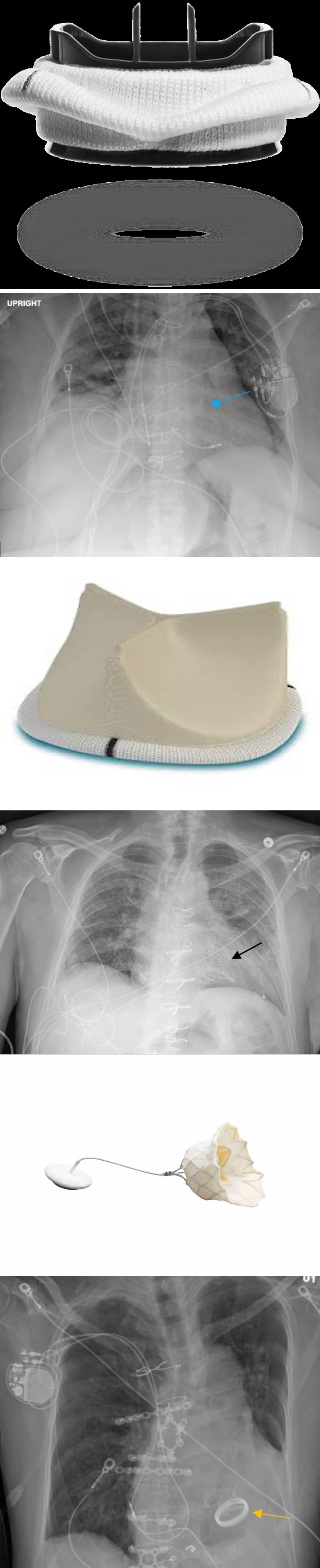
Figure 8a: Frontal chest radiograph shows a supra- annular aortic prosthetic valve (blue arrow).
Figure 8b: Trifecta valve photograph illustration. Cardiac pacemaker and respective wires are noted. Figure 8b is reprinted, with permission, from Abbot.
Figure 9a: PA chest radiograph showing aortic mechanical valve prosthetic (yellow arrow) shows bi-leaflet design. Cardiac pacemakers and respective wires are noted.
Figure 9b: On-X Aortic valve photograph illustration. Figure 9b is reprinted, Used with the Permission of Artivion, Inc.
Figure 10a: PA chest radiograph with transcatheter mitral valve implantation system (black arrow).
Figure 10b: Photograph illustration shows Tendyen device, it is a tri-leaflet prosthesis which has an inner frame and outer frame. Figure 10b is reprinted, with permission, from Abbot.
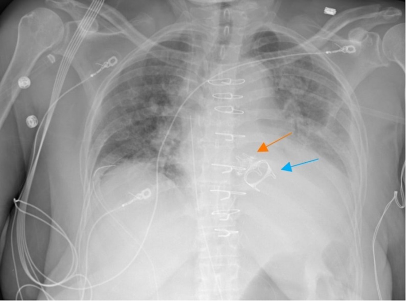
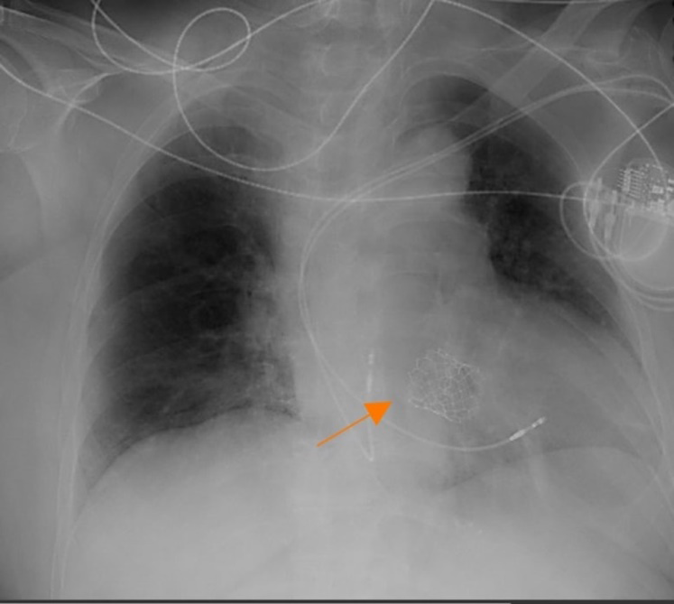
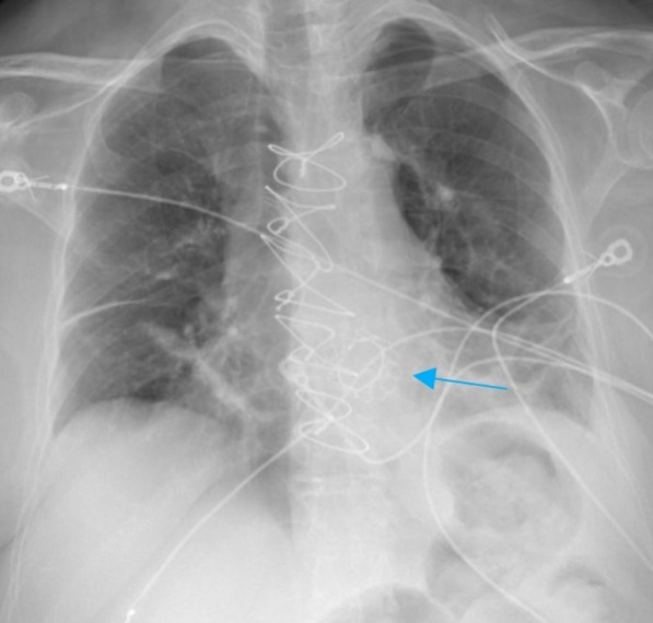
Figure 13a: Frontal AP chest radiograph (a) demonstrates ballon-expandable TAVR (blue arrow) in aortic position.
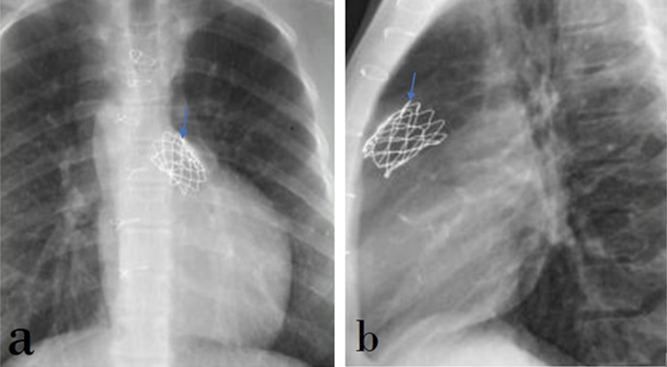
Figure 13b: Photograph of Sapien 3 aortic valve. Figure 13b reprinted, with permission, from Edwards Life Science.
Figures 15a & 15b: PA (a) and lateral (b) chest radiographs demonstrate transcatheter pulmonic valve replacement (blue arrows).
The Tendyne valve is a tri-leaflet porcine bioprosthetic mitral valve; it is a self-expanding prosthesis with a double- frame design. The shape of the Tendyne device conforms to the anatomical shape of the annulus, giving it more security to avoid migration [14]. The frame of the valve implant can be seen in chest radiograph in the mitral position (Figure 17). Annuloplasty devices are surgically sutured to the valve annulus to narrow or reshape this fibrous structure. Widening of a valve annulus can lead to insufficient coaptation of its leaflets and regurgitation. Annuloplasty devices are most commonly used to repair mitral and tricuspid valves. They may have a complete circular (ring) appearance or a C-shaped (incomplete ring) appearance on radiography [6, 15] (Figures 18a,18b,18c). The open portion of C-ringed annuloplasty devices usually faces the interventricular septum where the AV node resides to void irritation to this structure by the surgical sutures. Many annuloplasty rings are MR Safe, even in studies with 3T MRI machines, however some remain MR conditional [4].
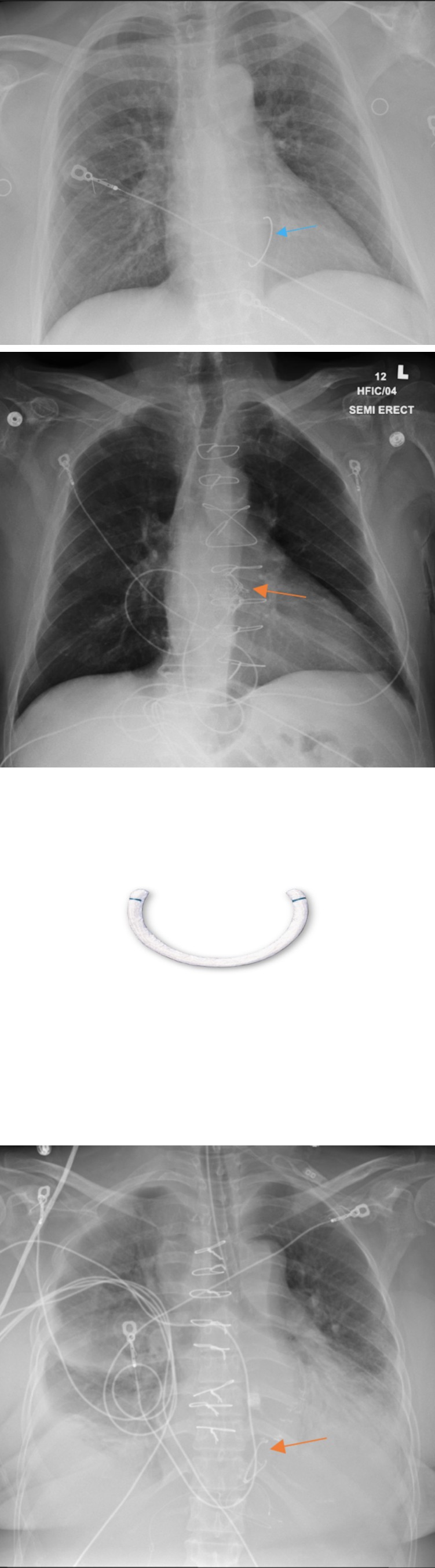
Figure 18a: PA chest radiograph demonstrates C-shape annuloplasty device in the tricuspid position (orange arrow).
Figure 18b: AP Chest radiograph demonstrates annuloplasty in mitral position (blue arrow).
Figure 18c: Open design Cosgrove-Edwards annuloplasty- ring photograph. Figures 18c reprinted, with permission, from Edwards LifeScience.
Potential complications of prosthetic valve devices include valvular or paravalvular regurgitation, dehiscence, endocarditis, paravalvular abscess formation, valve obstruction with thrombus or pannus, structural failure of the valve, pseudoaneurysm formation, aortic dissection, and mechanical hemolysis [16].Mitral clips are placed through a transcatheter approach to treat mitral regurgitation, Transcatheter Edge to Edge repair (TEER). These devices partially pins the tips of the leaflets mitral valve leaflets together in order to reduce the distance between the leaflets at systole and hence, decrease the regurgitant flow (Figure 19) [17]. These are considered MR conditional, up to 3T and SAR of 4 w/kg.
Closure and Repair Devices
Closure and repair devices are used to close or repair defects in the heart and major blood vessels such as closure of patent ductus arterisus (PDA), atrial septal defects (ASDs), patent foramen ovale (PFO), and ventricular septal defects (VSD). These devices are placed by transvenous or transarterial catheterization. Upon deployment, a self- expandable covered wire stent opens up giving the device its final functional shape, typically a dumbbell or a double umbrella shape, straddling the defect [1, 18] (Figures 20b,21b). PDA closure is performed in young patients and the device projects over the aortopulmonary window (Figure 20a). ASD/PFO closure devices are larger than PDA closure devices, and project over the base of the heart on lateral radiographs and to the right side of the cardiac silhouette on posterior-anterior views (Figure 21a). VSD closure devices are very similar to ASD/PFO closure devices, but its location is closer to the left margin of the cardiac silhouette on posterior-anterior radiographs, and more anterior on lateral views (Figures 22a,22b). PDA, ASD, PFO and VSD occluders are considered MRI conditional. Patients with MP35N cardiac occluders can have MR procedures at 1.5-Tesla or less any time after implantation. However, those with 304V stainless steel occluders should wait at least six weeks after implantation for better retention. This allows tissue ingrowth to enhance their hold [4].
Figure 20a: PA chest radiograph showing a PDA closure device (orange arrow).
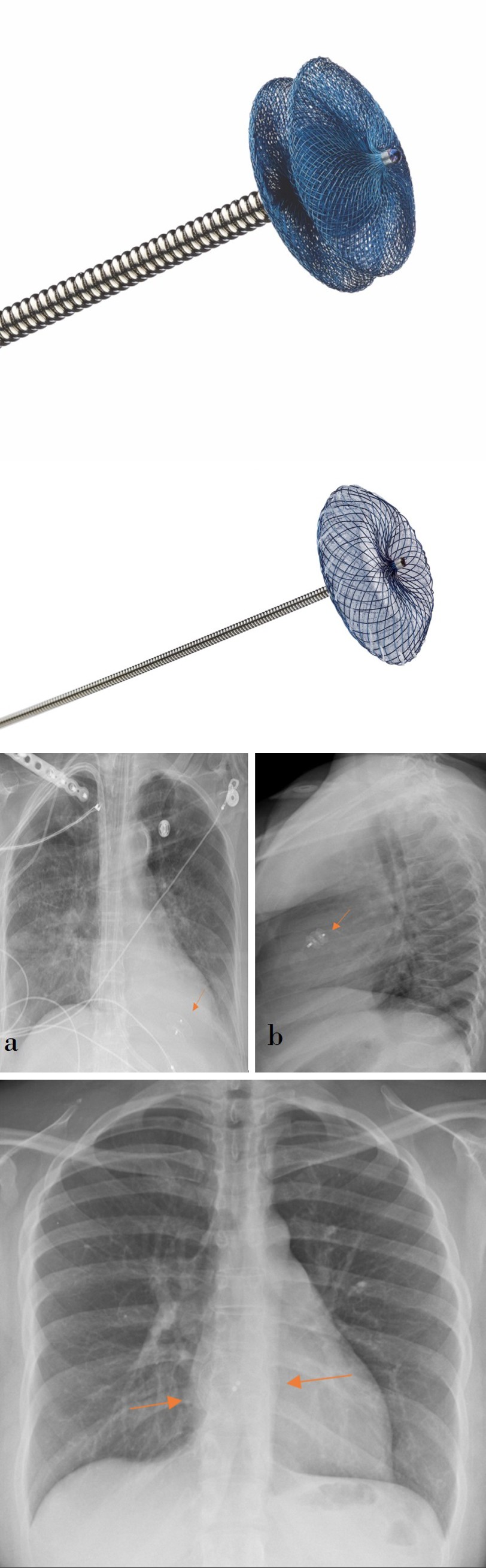
Figure 20b: Photograph of the Amplatzer Duct Occluder device (b), with dumbbell shape. (Figure 20b reprinted, with permission, from Abbot).
Figure 21a: PA chest radiograph showing an ASD closure device (orange arrows), shows double umbrella shape.
Figure 21b: Photograph of atrial septal defect closure device. Figure 21b reprinted, with permission, from Abbot.
Figures 22a & 22b: PA chest radiograph (a) and lateral (b) chest radiograph demonstrating a VSD closure device (orange arrow), projecting closer to the left cardiac margin.
Possible complications of closure devices include dislodgement and embolization of the device (typically secondary to choosing an undersized device or improper placement) which may require open surgical extraction [18]. Left atrial appendage (LAA) closure devices are placed in atrial fibrillation and it is an alternative for surgical ligation of the LAA. Stagnant flow within the LAA predisposes for clot formation which may dislodge causing arterial emboli [19]. Current devices are the Watchman LAA closure device, Amplatzer Amulet, and Amplatzer Cardiac Plug. LAA occlusion devices are delivered via a transvenous approach. The interatrial septum is punctured to access the left atrium and the self-expandable LAA closure device is deployed in the atrial appendage. This device appears along the left upper cardiac silhouette on posterior-anterior radiographs (Figures 23a,23b,23c,23d). Device embolization/migration is a potential complication of this procedure, in which the device is seen projecting on other locations such as at the mitral valve. These devices have an MR safety classification of conditional at 1.5 and 3T [4].
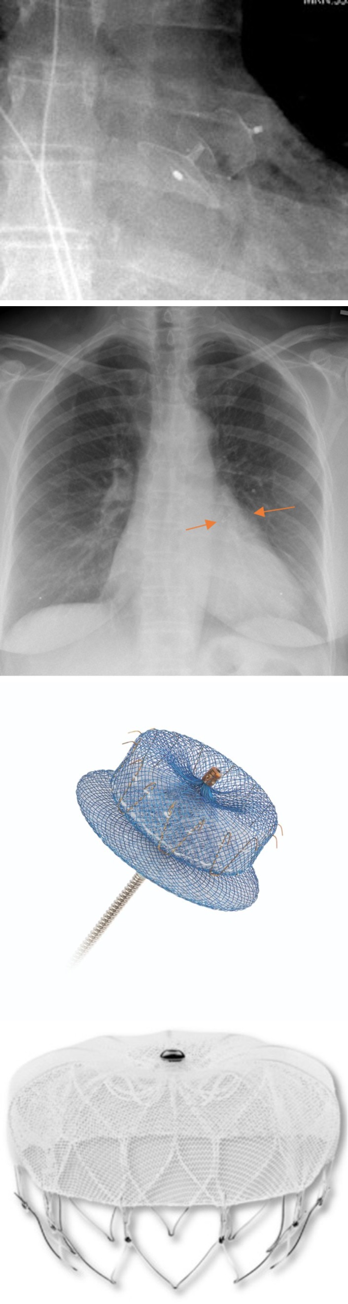
Figure 23a: PA Chest radiograph showing left atrial appendage Watchman closure device in the left upper cardiac silhouette.
Figure 23b: Photograph of Legacy WATCHMAN™ Left Atrial Appendage Closure Device. Figure 23b reprinted with permission, ©2023 Boston Scientific Corporation or its affiliates. All rights reserved.
Figure 23c: Magnified chest radiograph demonstrates Amulet left atrial appendage closure device.
Figure 23d: Illustration of Amulet device. Image 23d reprinted, with permission, from Abbot.
Aortic stent grafts are used for aortic aneurysm repair, treatment of aortic ulcerations, dissections, fistulae, and traumatic aortic injury. These devices consist of a self- expanding metallic stent covered with a graft fabric which establishes a functional lumen and ensures extraluminal portions of the stent are excluded from the circulation [20]. These stents can be placed anywhere in the thoracic aorta (Figure 24). Potential complications can occur secondary to occlusion of the aortic branches (stroke, spinal cord ischemia, left arm claudication, and downstream embolism), aortic perforation, graft migration, endoleak, graft infection, aortoesophageal fistulae and aortobronchial/aortotracheal fistulae [20]. Many aortic stent grafts are MR safe, however some still are MR conditional, so inquiring for specific devices is necessary.
Pressure Assist Devices
Mechanical circulatory support may be indicated in severe heart failure or cardiogenic shock. These devices may provide permanent cardiac support or may be utilized as a temporary measure until cardiac function is restored, or as a bridge to heart transplantation [6]. Extracorporeal membrane oxygenation (ECMO) is a temporary circulatory assist system used for severe lung and/or heart failure. This system consists of two large bore cannulas. The first cannula pulls blood from the venous system and sends it to an extracorporeal oxygenator that removes carbon dioxide and oxygenates the blood (i.e. performing lung functions). The second cannula may be placed into either the venous system (veno-venous ECMO), or to the arterial system "(veno- arterial ECMO)". "Veno-venous ECMO" (Figure 25) is used when there is sever pulmonary dysfunction with preserved cardiac functions (e.g. in acute respiratory distress syndrome (ARDS)). Veno-arterial ECMO is typically used when there is severe cardiac or a both cardiac and pulmonary dysfunction. Blood returning through the arterial cannula can have a high pressure sufficient to support the circulation [21, 22].
Additional ECMO types include the veno-veno-arterial system (VVA), in which two draining cannulas are placed in both the inferior and superior venae cava with the blood returning into a common iliac artery; veno-arterio-veno system (VAV) in which blood is drained from the inferior vena cava, and returned to both the common iliac artery and superior vena cava; or a single dual lumen venous catheter that pulls blood out the proximal lumen, and returns oxygenated blood through the distal lumen [21]. ECMO cannulas are large bore, ranging from 8F in infants to 31F in adults, and typically have a “ribbed” appearance on radiography [23]. The most common complication of ECMO is bleeding, which may be attributed to device-related coagulopathy or hemorrhage from vascular injury, commonly at insertion sites [21, 24]. Patients on ECMO therapy are consistently connected to external pumps, making MRI scans unsafe for this population.
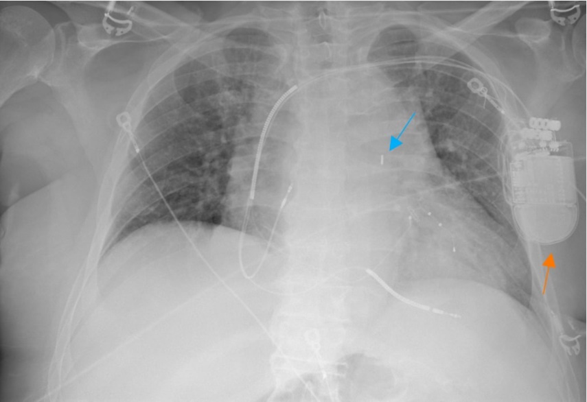
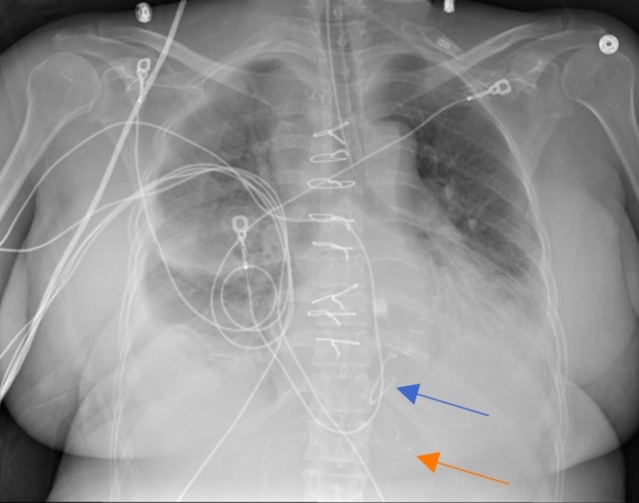
The intra-aortic balloon pump (IABP) is another temporary removable pressure assist device. IABP may be used in cardiogenic shock, acute myocardial infarction, and in patients having difficulty being weaned from cardiopulmonary bypass [24, 25]. These systems consist of a fusiform inflatable balloon (measuring up to 40 cm in length) that is inserted via femoral approach or via axillary approach, and coupled with electrocardiogram to time intermittent inflation and deflation cycles. During ventricular diastole the balloon inflates pushing blood into the coronary arteries and aortic arch branches resulting in increasing diastolic pressures. In systole, the aortic valve opens and the balloon deflates which decreases the cardiac afterload, ultimately supporting left ventricular functions [6, 22, 25]. IABP has a metallic marker at its tip. This distal metallic marker in the femoral approach and proximal metallic marker in the axillary approach should be positioned just below the origin of the left subclavian artery so that the abdominal part of the balloon terminates above the main branches of the abdominal aorta [26] (Figure 26a). Superior misplacement of the IABP can occlude branches of the aortic arch which increases the risk of embolism to the cerebral vessels (Figure
26b). Inferior misplacement can compromise flow to the splanchnic arteries (celiac, mesenteric and/or renal arteries) [25] (Figure 26c). Other possible complications include aortic intimal tearing, dissection, gas leak from balloon rupture, and hemolysis [25]. Patients with IABP need discontinuation of the therapy to get MR images since it is MR unsafe, this could lead to hemodynamic stability.
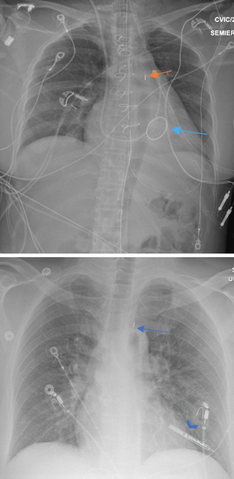
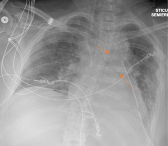
Figure 26a: AP chest radiograph that demonstrates adequately placed femoral approach IABP with distal metallic marker (orange arrow) overlaps aortic knob, left paraspinal lucency (blue arrow) corresponds to the inflated balloon during diastole.
Figure 26b: Frontal chest radiograph illustrates IABP misplacement (blue arrow) with upward migration, an implantable loop recorded is also noted (blue arrowhead).
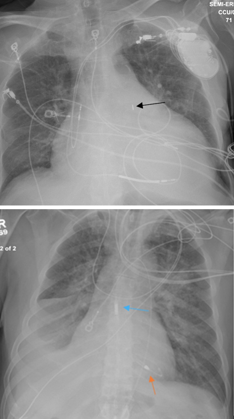
Figure 26c: Frontal chest radiograph demonstrates IABP downward misplacement (black arrow).
Percutaneously placed temporary Ventricular assist devices (VADs) are indicated for circulatory support of severe left heart failure. These devices are placed via arterial catheterization and placing the distal tip of this device is placed in the left ventricle and blood is pulled which also acts as the power cord. These LVADs are placed transarterially across the aortic valve, with the inlet to the pump is positioned in the left ventricle, and the outlet in the ascending aorta [24] (Figure 27). Potential complications include bleeding, hemolysis, device malfunction, valvular injury, and ischemia to the limb supplied by the accessed artery [27]. Ventricular assist devices are the mainstay of temporary and permanent mechanical circulatory support for patients with severe heart failure. VADs can support the functions of a single ventricle (right VAD (RVAD), or left VAD (LVAD)), or both ventricles [6]. Currently, all VADs are MR unsafe [4].
One style of temporary RVAD utilizes a dual lumen cannula pulling blood through one lumen (commonly placed in the right atrium or SVC) and pumping it back through a more distal lumen positioned in the pulmonary trunk [28] (Figure 28). These devices consist of a pump unit that is implanted into the patient, with an inflow cannula draining the left ventricle and an outflow cannula delivering blood back into the ascending aorta. A driveline connected to the pump extends outside the patient’s body and is connected to an external control unit and power source [29]. The cannulas are often radiolucent and may not be identifiable on radiography. The pump and its connecters are identifiable on chest radiographs (Figures 29,30a,30b). VAD complications include hemorrhage, thrombosis of the inflow or outflow cannula, distal embolism, renal failure, device failure, and infection [6, 29].
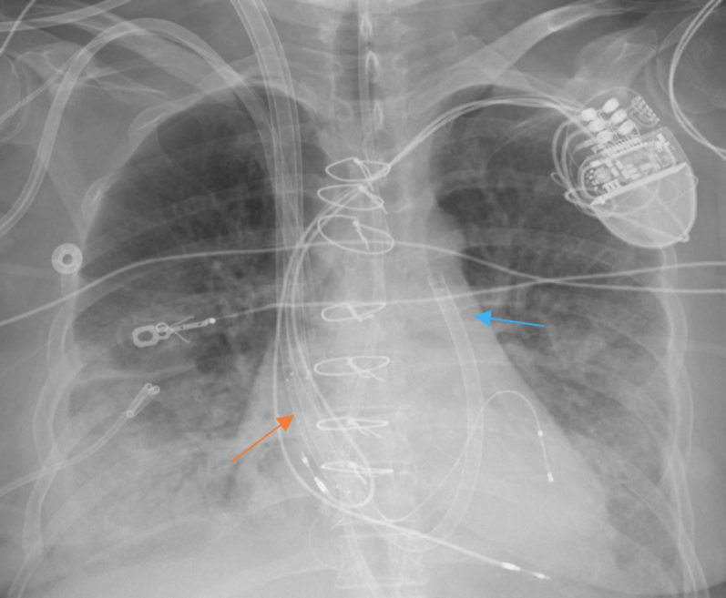
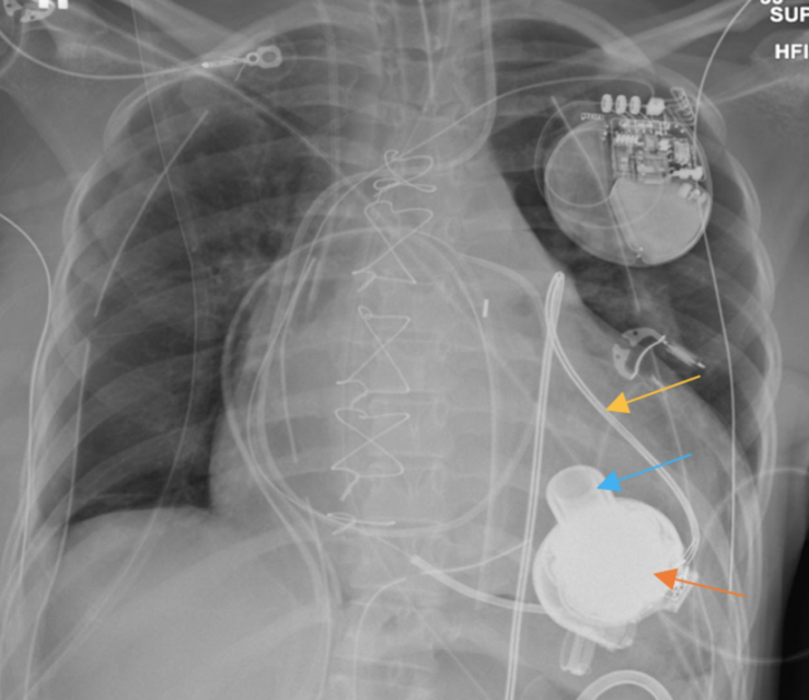
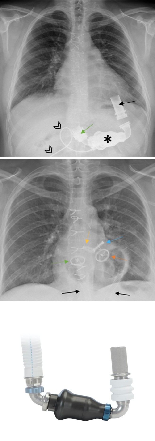
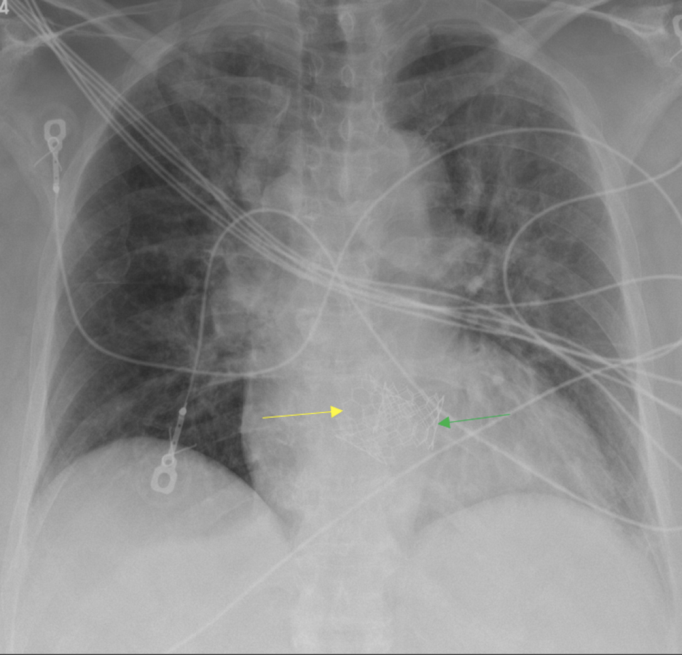
Figure 30a: PA chest radiograph demonstrates HeartMate II LVAD and its parts: inflow canula (black arrow), impeller unit (asterisk), outflow cannula (green arrow), and driveline (black arrowheads).
Figure 30b: A graphic of HeartMate II device (b). Sternotomy wires are noted. Figure 30b reprinted, with permission, from Abbot respectively.
Total artificial heart (TAH) may be implanted in patients with severe biventricular heart failure without an immediate opportunity for cardiac transplantation. This device is used to replace the cardiac function as a bridge to heart transplantation [6, 30]. TAH requires resection of both ventricles and implantation of two pumps in their locations receiving blood from the mitral and tricuspid valves and pumping it back into the ascending aorta and pulmonary trunk, respectively. Drivelines exiting these pumps extend to an extracorporal control unit [30] (Figure 31). Complications of TAHs include thromboembolic events, infection, bleeding, renal failure, and hemolysis [31]. Due to its nature as an external cardiac assist device, the TAH always has an external pump connected, which makes it unsafe for MR studies [4].
Figure 31: PA chest radiograph that shows correct implantation of total artificial heart device and its components; the aortic outflow graft [acting aortic valve] (blue arrow), pulmonary artery outflow graft [acting pulmonic valve] (yellow arrow), acting mitral valve (orange arrow), acting tricuspid valve (green arrow) and pneumatic drivelines (black arrows) that extend to an extracorporeal control unit.
Left Ventricular Partitioning Devices Include the Parachute: The Parachute is deployed in the left ventricle, and it is used to isolate the dysfunctional regions of the ventricle after an anterior wall myocardial infarction. The PARACHUTE trial demonstrated significant and sustained LV volume reduction, and improvement in hemodynamics and functional capacity 12 months after implantation [32]. This device has an umbrella-shaped frame that tapers to a foot. On chest radiograph, the “foot” of the device is seen on the apex of the LV (Figures 32a,32b) any other variation could indicate migration or misplacement. Although this device has been discontinued and is no longer in use, older patients may present with it and must be differentiated from Tendyne TMVR.
Figures 32a & 32b: Frontal chest radiograph (a) demonstrates parachute device (orange arrow) adequately placed in near the LV apex, magnified (b) Parachute device.
Cardiac Monitoring Devices
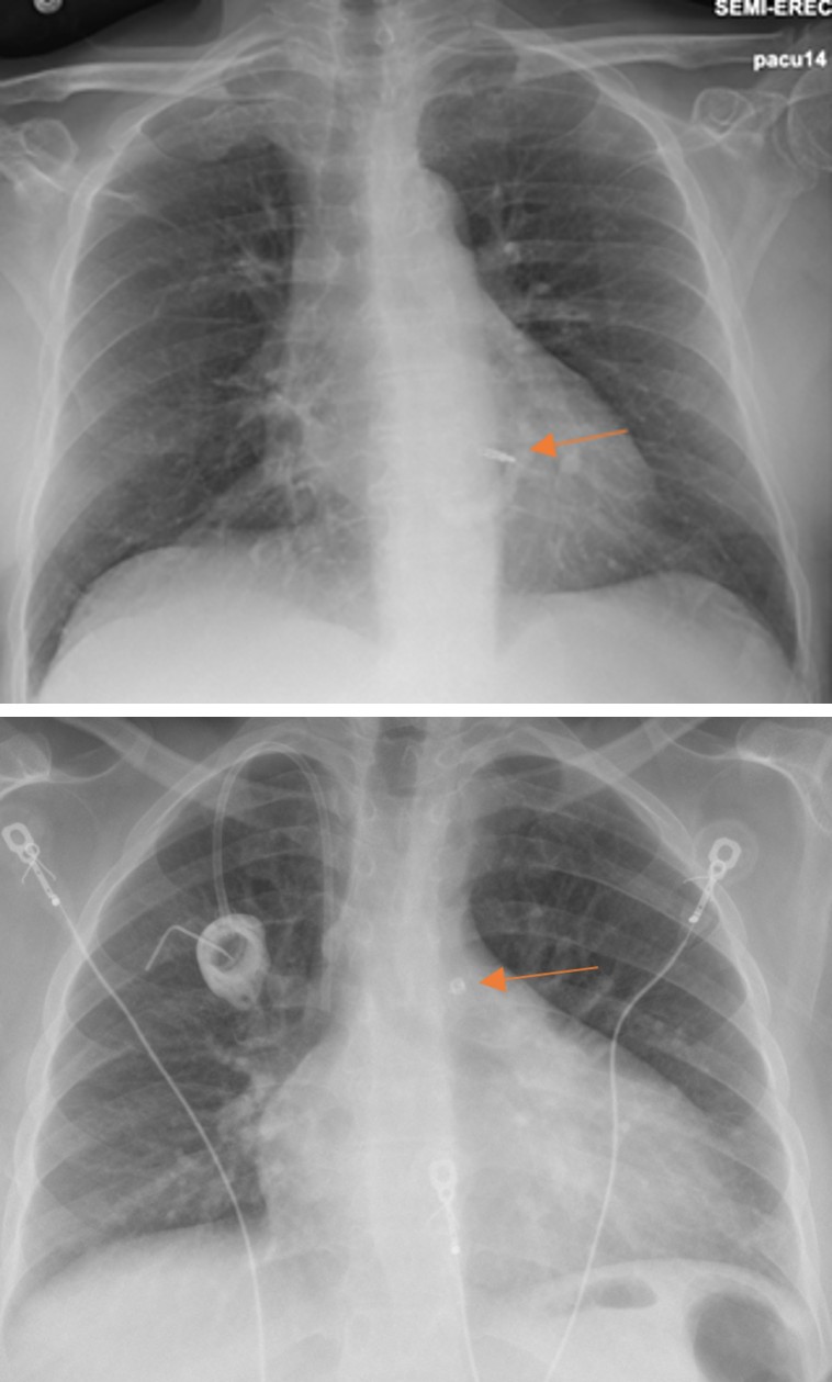
The implantable loop recorder is used for recording cardiac rhythm for long durations reaching as long as 3 years [6, 33]. Implantable loop recorders are leadless devices measuring less than 2 inches in length that are implanted in the anterior chest wall (Figure 33). The most common complication of these devices is infection [33]. These devices are categorized as MRI conditional, there must be precautions with the local transmit coils [4]. Intravascular artery pressure sensor is a wireless device used for monitoring pulmonary arterial pressures. This device is placed in the distal pulmonary arteries where it records pressure readings (Figures 34a,34b). Rising pulmonary artery pressures detected by these devices may indicate left ventricular dysfunction which helps direct patient management. Potential complications of these devices include arrhythmias, bleeding, device embolization, hematoma, infection, thromboembolic events, and thrombus formation. It is MR conditional, up to 3T and SAR of 2.9 w/ kg 4 [34, 35].
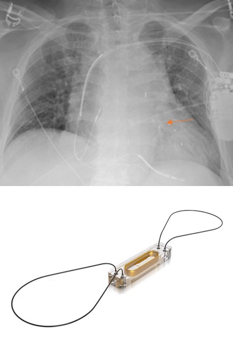
Figure 34a: Chest radiograph demonstrates CardioMEMS device in the left lower lobe pulmonary artery branch (orange arrow).
Figure 34b: CardioMEMSTM wireless pulmonary artery hemodynamic monitoring sensor. Figure 34b reprinted, with permission, from Abbot.
Conclusion
Cardiac devices are very commonly encountered in the medical setting as they treat a variety of cardiac abnormalities. It plays a fundamental role in monitoring cardiac health, evaluating device placement, and identifying potential complications, ensuring prompt recognition and treatment for optimal patient care. In many medical scenarios, chest radiographs are the preferred imaging modality and play a pivotal role in the evaluation of chest devices, especially in intensive care units. Additionally, chest radiographs have quick acquisition, which makes them suitable for evaluating migration and other complications that can occur with these devices. Radiologists must be familiar with these devices’ normal position to detect abnormalities in the many chest radiographs they encounter.
References
-
American College of Radiology. ACR Appropriateness Criteria®.
-
Aguilera AL, Volokhina YV, Fisher KL (2011) Radiography of cardiac conduction devices: a comprehensive review. Radiographics 31(6): 1669-1682.
-
Costelloe CM, Murphy WA, Gladish GW, Rozner MA (2012) Radiography of pacemakers and implantable cardioverter defibrillators. AJR Am J Roentgenol 199(6): 1252-1258.
-
Frank GS THE List. MRI Safety Home.
-
Kadish A, Mehra M (2005) Heart Failure Devices. Circulation 111(24): 3327-3335.
-
Hunter TB, Taljanovic MS, Tsau PH, Berger WG, Standen JR (2004) Medical devices of the chest. Radiographics 24(6): 1725-1746.
-
Kaya E, Rassaf T, Wakili R (2019) Subcutaneous ICD: Current standards and future perspective. Int J Cardiol Heart Vasc 24: 100409.
-
Bhatia N, El Chami M (2018) Leadless pacemakers: a contemporary review. J Geriatr Cardiol 15(4): 249-253.
-
Knops RE, Vivek YR, James E, Rahul D, Derek VE, et al. (2023) A Dual-Chamber Leadless Pacemaker. N Engl J Med 388(25): 2360-2370.
-
Edmunds LH (2001) Evolution of prosthetic heart valves. Am Heart J 141(5): 849-855.
-
Schaefer A, Conradi L (2020) Transcatheter Mitral Valve Replacement for Degenerated Bioprosthetic Valves and Failed Annuloplasty Rings. Surg Technol Int 37: 185-190.
-
Choo WS, Steeds RP (2011) Cardiac imaging in valvular heart disease. Br J Radiol 84(Spec Iss 3): S245-S257.
-
Landay MJ, Estrera AS, Bordlee RP (1992) Cardiac valve reconstruction and replacement a brief review. Radiographics 12(4): 659-671.
-
Ahmed A, Aziz TAA, AlAsaad MMR, Majthoob M, Toema A (2023) Transcatheter mitral valve implantation with Tendyne System Ten Years since the First In-Human Implant A systematic review. J Cardiothorac Surg 18(1):
-
Rausch MK, Bothe W, Kvitting JP, Swanson JC, Miller DC, et al. (2012) Mitral valve annuloplasty: a quantitative clinical and mechanical comparison of different annuloplasty devices. Ann Biomed Eng 40(3): 750-761.
-
Pham N, Zaitoun H, Mohammed TL, DeLaPena-Almaguer E, Martinez F, et al. (2012) Complications of Aortic Valve Surgery Manifestations at CT and MR Imaging. RadioGraphics 32(7): 1873-1892.
-
Maisano F, Taramasso M (2020) Percutaneous mitral valve leaflet repair ongoing directions and future perspectives. EuroIntervention 16(10): 803-807.
-
Mandell VS, Nimkin K, Hoffer FA, Bridges ND (1993) Devices for transcatheter closure of intracardiac defects. AJR Am J Roentgenol 160(1): 179-184.
-
Gary GCH, Bhat A, Davis L, Denniss AR (2014) Percutaneous transcatheter left atrial appendage closure devices role in the long-term management of atrial fibrillation. Heart Lung Circ 23(5): 407-413.
-
Therasse E, Soulez G, Giroux MF, Perreault P, Bouchard L, et al. (2005) Stent-graft placement for the treatment of thoracic aortic diseases. Radiographics 25(1): 157-173.
-
Napp LC, Kuhn C, Hoeper MM, Vogel-Claussen J, Haverich A, et al. (2016) Cannulation strategies for percutaneous extracorporeal membrane oxygenation in adults. Clin Res Cardiol 105: 283-296.
-
Simon MA (2013) Assessment and treatment of right ventricular failure. Nat Rev Cardiol 10(4): 204-218.
-
Das S, Gupta S, Das D, Dutta N (2022) Basics of extra corporeal membrane oxygenation: a pediatric intensivist s perspective. Perfusion 37(5): 439-455.
-
Khan MH, Corbett BJ, Hollenberg SM (2014) Mechanical circulatory support in acute cardiogenic shock. F1000prime Rep 6: 91.
-
Hyson EA, Ravin CE, Kelley MJ, Curtis AM (1977) Intraaortic counterpulsation balloon: radiographic considerations. AJR Am J Roentgenol 128(6): 915-918.
-
Mebazaa A, Gheorghiade M, Zannad FM, Parrillo JE (2008) Acute Heart Failure. Springer London.
-
Batsides G, Massaro J, Cheung A, Soltesz E, Ramzy D, et al. (2018) Outcomes of Impella 5.0 in Cardiogenic Shock A Systematic Review and Meta-analysis. Innovations (Phila) 13(4): 254-260.
-
Kazui T, Tran PL, Echeverria A, Jerman CF, Iwanski J, et al. (2016) Minimally invasive approach for percutaneous CentriMag right ventricular assist device support using a single PROTEKDuo Cannula. J Cardiothorac Surg 11(1): 123.
-
Roberts SM, Hovord DG, Kodavatiganti R, Sathishkumar S (2015) Ventricular assist devices and non-cardiac surgery. BMC Anesthesiol 15: 185.
-
Arabia FA (2020) The Total Artificial Heart Where Are We? Cardiol Rev 28(6): 275-282.
-
Cook JA, Shah KB, Quader MA, Cooke RH, Kasirajan V, et al. (2015) The total artificial heart. J Thorac Dis 7: 2172- 2180.
-
Silva G, Melica B, Pires de MG, Sousa O, Bettencourt N, et al. (2012) Percutaneous implantation of a ventricular partitioning device for treatment of ischemic heart failure: Initial experience of a center. Rev Port Cardiol 31(12): 795-801.
-
Vilcant V, Kousa O, Hai O (2023) Implantable Loop Recorder. StatPearls [Internet]. Treasure Island (FL): StatPearls Publishing.
-
Mangi MA, Nesheiwat Z, Kahloon R, Moukarbel GV (2020) CardioMEMSTM System in the Daily Management of Heart Failure Review of Current Data and Technique of Implantation. Expert Rev Me Devices 17(7): 637-648.
-
Abraham WT, Adamson PB, Bourge RC, Aaron MF, Costanzo MR, et al. (2011) Wireless pulmonary artery haemodynamic monitoring in chronic heart failure a randomised controlled trial. Lancet 377(9766): 658- 666.
- Ultrasound Guided Therapeutic Nerve Blocks
- Cyclops Lesion Without ACL Reconstruction: A Rare Case in a Patient with Intact Anterior Cruciate Ligament and Tibial Plateau Fracture
- Dosimetric Comparison between Two Dose Calculation Algorithms in SBRT Treatment of Lung Cancer in Ring-based and C-arm Radiation Therapy Equipment
- Adolescent Testicular Adrenal Rest Tumors: A Case Report and Review of the Literature
- Giant Intrathoracic Lipoma: A Rare Presentation
- Image of a Right Renal Angiomyolipoma Complicated by Hemorrhage