Fabrication of Carbon Based Nanostructured Materials on Si/SiO2 Substrate and Their Growth Mechanism over Different Catalysts
In this study, carbon based nanostructured material was synthesized by catalytic chemical vapor deposition (CCVD) technique using metallic (Ni, Co) and Semiconductor (FeCl3.6H2O/ZnO) catalysts on Si/SiO2 substrates. Acetylene (C2H2) and argon were utilized as a precursor and carrier gases respectively. The changes in surface morphology, crystal structure, elemental distribution, surface roughness and crystalline character were observed by scanning electron microscopy (SEM), transmission electron microscope (TEM), energy dispersive x-ray spectroscopy (EDS), atomic force microscopy (AFM) and Raman spectroscopy respectively. The results show the dependence of carbon nanostructured materials growth on Si/SiO2 substrates using catalysts; Ni, Co and FeCl3.6H2O/ZnO found to be in the range of 10-20 min at 900/1100 ºC temperature. This study can be fruitfully employed for the fabrication of Nano-sensors.
Introduction
Recently, fabrication of nanomaterials for technological development [1, 2, 3] is in trend, which is a clear indication of miniaturization of electronic devices in recent years, not only this technology reduces the size but also, the developed materials have superior performance than the bulk counterparts. This advancement in performance of the materials is due to small size, which allows electron confinement leading to quantum effects [4]. Nanomaterials have been generating a great interest in; electronics, environmental and medical applications [5, 6, 7].
Since the discovery of carbon nanotube (CNT) [8], this material is creating a lot of attention because of its structural, thermal, mechanical, electrical and chemical properties [9]. Long and slender C-C covalently bonded structure with large surface area and hexagonal networking makes CNT a very unique material for various applications. Therefore, CNT’s attracts much attention in the field of sensors, actuators, transistors, and energy storage devices [1]. Moreover, it can also be adopted in the formation of hybrid materials, which makes them promising in optoelectronic, environmental and medical applications [2, 6, 7].
Considering previous research conducted in the field of CNT fabrication, researchers have found CNT’s of different shapes, size and surface morphology depending on their synthesis method, catalyst and carbon source [10, 11, 12, 13, 14, 15, 16, 17, 18, 19, 20, 21, 22, 23]. Catalytic chemical vapor deposition (CCVD) is the most commonly utilized technique for CNT production, where transition metals like Ni, Co, Fe or their alloys are used for catalytic decomposition. Talking about the carbon source several sources have been investigated for the production of CNT’s in combination with catalyst. At the initial stage of growth, the accumulation of decomposed carbon is totally dependent on the catalyst and the growth temperature [12, 13, 14, 15, 16, 17].
The growth of CNT’s on Si/SiO2 substrate is very practical and essential for the optoelectronic devices and environmental applications in sensors, integrated circuits and water purification [18]. Unique characteristics of SiO2 (stability, temperature resistant, electrical insulator) makes them very important for several applications and well- defined local structure of SiO2 provides a decent platform for device fabrication.
Different mechanisms proposed for the growth of CNT are based on the reaction conditions are often contradicting on the basis of shape. The influence of the deposition temperature and catalyst used, affects the morphology of the CNT growth on silicon surface, the increase of the temperature for growth of CNT forms a thin to thick nano- worms of which diameter varies between 25 to 1 µm in size [14, 18, 24, 25, 26, 27, 28, 29]. The internal diameter and number of walls formation also depends on the catalyst used as well the gases introduced during growth like H2, the role of H2 is to make the reaction rate faster as well as the linear alignment of CNTs. Usually found that the carbon structures grown at higher temperature consists of a nanotube core and an additional layer of amorphous or polycrystalline carbon, which is clearly mentioned by many researchers [11]. Researchers also mentioned that CNT growth is a very fast process and the growth takes place during first 5 minute but the same times found that the quantity of growth at initial stage is quite low as well as also affects the length and shape of grown CNT [10, 14, 16, 19, 21, 26, 27, 28, 29].
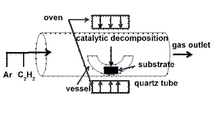
Our idea of CNT growth on Si/SiO2 substrate is to optimize the growth conditions and to choose a better catalytic candidate for the fabrication of optoelectronic and environmentally applicable devices. In this paper we report the growth of carbon nanotubes on metals (Ni, Co) and semiconductor (FeCl3.6H2O/ZnO) catalysts using CCVD technique. CNT growth was performed inside a quartz tube using ultra-pure acetylene (C2H2) gas as a carbon source, argon (Ar) as a carrier gas and the growth temperature of 900/1100oC for 10-20 min growth time. The catalysts; Ni and Co were deposited using physical vapor deposition (PVD) technique at nonmetric dimension, while ZnO catalyst was decomposed together with the acetylene flow in the quartz chamber onto Si/SiO2 substrate coated with FeCl3.6H2O by the use of spin coting technique. The flow of carrier gas was constant for all the experiments setups while the oven temperature and precursor flow were varied on the performing experiments.
Experiment
First, Si/SiO2 substrates were cleaned for removal of organic and metallic contamination from the surface using NH4OH:H2O2:H2O (1:1:5) at 75°C for 10 min, and washed with deionized (DI) water. Then substrates were immerged and cleaned by HCl: H2O2: H2O (1:1:5) for 15 min for removal of metal particle on the surface and washed several times using DI water and finally spray compressed gas was used to avoid any spot formation.
To enhance the CNT growth on Si/SiO2 substrate a thin layer of catalyst was plated by applying physical vapor deposition (PVD) technique, which is well studied technique for the formation of homogeneous and fine layer of catalyst. Metal catalysts, Ni, and Co (3 nm thick each) were deposited by applying 28 A and 30 A current respectively in a vacuum chamber. In another step, 10-2 molar solution of FeCl3.6H2O was deposited on silica substrate by applying spin coating technique at 5000 RPM and medium acceleration for 60 sec., which forms around 1 nm layer. For CNT growth, catalyst deposited silica substrate was placed in a quartz tube oven on alumina boat using Argon as a carrier and acetylene as a precursor gas. Here we studied the CNT growth based on three parameters; growth time, growth temperature and catalyst, as shown in table 1. In case of ZnO-CNT composite, growth the ZnO powder was vaporized at 1100°C in quartz tube as the melting point of ZnO is ~1080 °C. Prior to CNT growth, the quartz tube was purged by the flow of Ar gas, 85 sccm for 15-20 minutes then the oven temperature was increased with the flow of Ar. While the temperature reach to the label as mentioned in the table 1 the flow of C2H2 gas was introduced in the oven at 5-8 sccm flow rate. Figure 1 show the experimental setup used in our experiments. To maintain the inert environment during the experimental procedure Argon gas supply was kept continuous until the oven temperature gradually decreases to the ambient temperature. The characterization of CNT grown was observed and confirmed by applying XRD, AFM, SEM, EDS, TEM and Raman techniques.
Results and Discussion
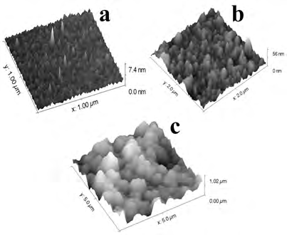
The thickness of the deposited catalyst was found ~3 nm by using ellipsometry technique. After catalyst deposition CNT growth was performed in a quartz tube oven at 750- 900°C temperature using C2H2 (acetylene gas) as a precursor and Ar as a carrier gas (Figure 1). The flow of carrier gas was constant while the oven temperature and precursor flow was varied in the performed experiment. Initially Ar gas was passed for 15 min to make the quartz tube an inert medium, then the temperature was increased to the desired value. After attaining the desired temperature, acetylene gas was passed in the quartz tube oven for CNT growth as mentioned in the Table 1. Figure 2 shows the atomic force microscopic images of catalytic deposition and CNT growth roughness on the silica substrate. Figure 2a show Ni catalyst roughness on silica substrate about 0.4 nm while after CNT growth the roughness was found 6.2 nm (Figure 2b) while on Co catalyst the roughness was about 166 nm (Figure 2c).
| Catalyst | Growth temp. (°C) | Growth time (Min.) |
|---|---|---|
| Ni | 900 | 10/20 |
| Co | 10/20 | |
| FeCl .6H O/ZnO 3 2 | 1100 | 10 |
Table 1: Sample details and CNT growth parameters for different samples.
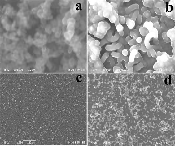
Figure 3 shows the scanning electron micrographs (SEM) of the grown CNT with different catalysts. The temperature and time of growth found to be very important and affects the shape diameter and quantity of CNT formation. Fig. 3 shows that higher growth time ~ 20 min an excessive black layer has been found and growth time in between 10-20 min, the homogeneous formation of CNT occurs while the growth time ≤ 10 min the CNT formation didn’t occur. When the CNT growth ceases due to catalyst poisoning with excess carbon that supersaturated metal-carbon assembly might crystallize in carbide, oxide or silicates because of silica supported growth. The possibility of distortion in the lattice constant value might happen because the lattice constants vicinity of metal and their compounds as well small-size effect of formation during CNT growth. Moreover, catalyst provides stiffness and mechanical reshaping during CNT growth process that that there is feasibility of metal catalysts to be in liquid state during catalytic decomposition. However, this shape distortion occurs due to relative displacement of different atomic layers in solid state due to the large forces exerted by the surrounding CNT in the growth stage.
When a hydrocarbon vapor comes in contact with the hot metal-particles, first decomposes into carbon and carbon gets dissolved into the metal. After reaching the carbon-solubility limit the dissolved carbon precipitates out and crystallizes cylindrically without any enclosed bonding, which is energetically very stable. Meanwhile this decomposition process releases some heat to metal exposed zone while crystallization absorbs some heat from precipitation zone. When the catalyst-substrate interaction is weak hydrocarbon decomposes on top surface of the metal, carbon diffuses down through the metal and CNT precipitates out across the bottom pushing the whole catalyst off the substrate called as tip-growth. In the other case, when the catalyst-substrate interaction is strong, initial hydrocarbon decomposition and carbon diffusion take place similar to that in the tip-growth case, but the CNT precipitation fails to push the metal particle up; so the precipitation is compelled to emerge out from apex of the catalyst. Subsequently, hydrocarbon decomposition takes place on the lower peripheral surface of the catalyst and carbon diffuses upward. Thus CNT growth occurs, catalyst rooted on its base called as base-growth model. The growth of CNT has been performed with ZnO semiconductor because of its wide band gap and potential applications in optoelectronics and unique sensing behavior, which might change emission spectra and improve the crystallinity of grown hybrid nanostructure. The use of ZnO catalyst for CNT growth is applicable for sensing device applications because of its band illumination with photons. Thus, there might be the possibility of two reactions; oxidation of generated holes and electron reduction simultaneously. The degradation rate can be easily enhanced by the reduction of e-h pair recombination, which can prevent the clumping and increased the adsorption capacity.
The above results show that the chemical reaction/ diffusion between catalysts and substrates impairs the activity of the catalysts and while incorporated with carbon form a CNT-metal composites structure depending on their stability and catalytic property, many researchers mentioned [30] that all metal powders are possible to be used as catalyst carrier for CNT growth by CCVD. However, we can see clearly that the formation of the shapes like tubular, spinal, capsule or tubic structure depends on the growth temperature and precursor used.
Figure 4 shows the energy dispersive X-ray spectra and mapping of the prepared metal and semiconductor based material and their composition, which confirms the presence of deposited catalysts in the fabricated carbon structured material.
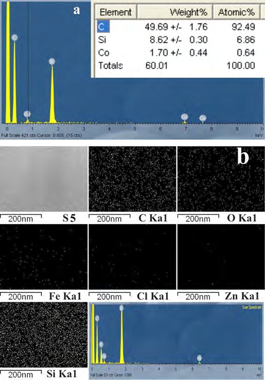
Figure 5 predicts the transmission electron microscopy (TEM) images of CVD growth of CNT on Ni, Co, Au and ZnO catalysts at different time and temperature. TEM images shows clearly the mechanism for CVD growth of CNT for Au, Ni and Co catalysts were quite different, Ni particles got accumulated on edge of grown CNT and the end shows pin shape structure covered with Ni metals while in case of Co the upper edge is open and circular. The presence of Ni and Co catalysts on the edges and inside can also be seen by the electron diffraction pattern, which also confirmed by the “CaRIne Crystallography” software program. Fig. 5d shows the multilayers hexagonal structure, which proves the mutilayed CNT growth. Formation of black layers inside the CNT is happening because the absence of H2 gas, which increases the reaction rate for the carbon nanotube formation.
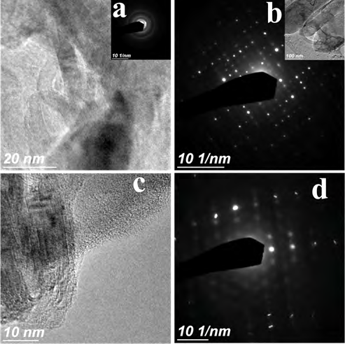
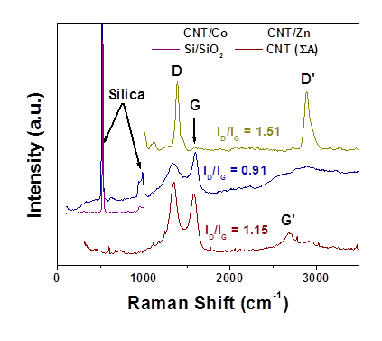
Figure 6 shows the Raman spectra of grown CNT using laser 532, which is also compared with the pristine MWCNT of Sigma-Aldrich using 514.5 nm laser beam. The crystalline graphite proceeds the disordered structure (D band) at ~1350 cm-1 and the vibrational mode at 1585 cm-1 because of the sp2 orbital domain of the carbon (G Band) in case of ZnO based carbon structure growth while D band is absent in Co based growth because of the selection rule of perfect graphite structure which is forbidden. Therefore, on metal catalyst based growth the its is very hard to confine the amorphous and crystalline carbon growth. The results show the similar Raman shift and the two strongest peaks of D and G band shows the clear formation of CNT growth on Co and ZnO based catalysts. The D band peaks observed at 1390, 1336 cm-1 and G band at 1589 and 1597 cm-1 for Co and ZnO based CNT growth respectively, which was in close proximity to pristine Sigma Aldrich MWCNT of 95 % purity of D and G band peaks; 1348, 1579 cm-1. ID/IG value of grown CNT was 1.51 and 0.91 for Co and ZnO based catalytic growth. Since the disordeness of the graphite like system increases with the preparation temperature that is why the ID/IG values are higher in case of Co based CNT growth compared to the ZnO based also the second ordered D peaks are visible in Co based growth while not in the ZnO based CNT growth.
Conclusions
In this paper it was demonstrated that CNT can be grown on Si/SiO2 substrate depositing different metal and semiconductor catalysts using acetylene as a carbon source at 900 & 1100°C temperature. The uniformity of the growth process, amount of impurity and the shape of the growth nanoparticles depend on growth time and temperature. Lower flow rate and lesser the time makes the nanocomposite growth more separated and uniform while the higher the flow rate and growth time make inhomogeneous and variability in the morphology. The thickness of the deposited catalyst particles makes a crucial role in the formation and shape of the nanostructured materials, as thinner the catalyst thickness the formation of the composite materials was helical while catalyst thickness is thick the shape is capsule/ worm type structure.
References
-
Nguyen LQ, Phan PQ, Duong HN, Nguyen CD, Nguyen LH (2013) Enhancement of NH3 Gas Sensitivity at Room Temperature by Carbon Nanotube-Based Sensor Coated with Co Nanoparticles. Sensors 13(2): 1754-1762.
-
Xingxing Yu, Tianyi Hua, Xiang Liu, Zhiping Yan, Peng Xu, et al. (2014) Nickel-Based Thin Film on Multiwalled Carbon Nanotubes as an Efficient Bifunctional Electrocatalyst for Water Splitting. Appl Mater Interfaces 6(17): 15395-15402.
-
Tiwari DK (2013) Nanocrystalline Nickel Cobalt Ferrite (Ni1/2CO1/2Fe2O4) For Electromagnetic Interference (Emi) Shielding Applications. Nano Studies 8: 53-62.
-
Emil Roduner (2006) Size matters: why nanomaterials are different. Chem Soc Rev 35(7): 583-592.
-
Moritz M, Geszke M (2012) Application of nanomaterials in medical sciences. CHEMI 66(3): 219-226.
-
Phong AT (2009) Carbon nanofibers and carbon nanotubes in regenerative medicine. Advanced Drug Delivery Reviews 61(12) 1097-1114.
-
Tiwari DK (2014) Interfacing carbon nanotubes (CNT) with plants: enhancement of growth, water and ionic nutrient uptake in maize (Zea mays) and implications for nanoagriculture. Applied Nanoscience 4(5): 577-591.
-
Sumio I (1991) Helical microtubules of graphitic carbon. Nature 354: 56-58.
-
Satoru Suzuki (2013) Physical and Chemical Properties of Carbon Nanotubes, INTECH Publication.
-
Munther IK, Jean LM (2009) Production of Carbon Nanotubes-Nickel Composites on Different Graphite Substrates. FDMP 5(2): 123-136.
-
Yung Joon Jung (2003) Mechanism of Selective Growth of Carbon Nanotubes on SiO2/Si Patterns. Nano Letters 3(4): 561-564.
-
Kliea RK, Ciuparub D, Pfefferleb L, Zhua Y (2004) Multi- walled carbon nanotubes on amorphous carbon films. Carbon 42(10): 1953-1957.
-
Cui H, Eres G, Howe JY, Puretkzy A, Varela M, et al. (2003) Growth behavior of carbon nanotubes on multilayered metal catalyst film in chemical vapor deposition. Chemical physics letters 374(3-4): 222-228.
-
VeríssimoI C, MoshkalyovI SA, Antônio Ramos CS, Gonçalves JL, Alves OL, et al. (2006) Different Carbon Nanostructured Materials Obtained in Catalytic Chemical Vapor Deposition. J Braz Chem Soc 17(6): 1124-1132.
-
Sasaki H, Sasaki T, Tanabu Y, Hatanaka S, Fujita S (2010) Investigation of CNT Growth by Substrate Temperature Control Using Thermal CVD Method. J Nanosci Nanotechnol 10(6): 3915-3918.
-
Toboonsung B, Singjai P (2008) Growth Conditions for Carbon Nanotubes and Helical Nanofibers on Copper Substrates Using Sparked Catalysts. Advanced Materials Research 55-57: 561-564.
-
Shaijumon MM, Ramaprabhu S (2003) Synthesis of carbon nanotubes by pyrolysis of acetylene using alloy hydride materials as catalysts and their hydrogen adsorption studies. Chemical Physics Letters 374(5-6): 513-520.
-
Allaedini G, Aminayi P, Tasirin SM (2015) The Effect of Alumina and Magnesia Supported Germanium Nanoparticles on the Growth of Carbon Nanotubes in the Chemical Vapor Deposition Method. Journal of Nanomaterials 501: 961231.
-
Zhao N, Chunnian H, Zhaoyang J, Jiajun L, Yongdan L (2006) Fabrication and growth mechanism of carbon nanotubes by catalytic chemical vapor deposition. Materials Letters 60(2): 159-163.
-
Christian PD, Kenneth V (2005) Growth mechanism of vapor phase CVD-grown multi-walled carbon nanotubes. Carbon 43(12): 2608-2617.
-
Chunnian H, Naiqin Z, Xiwen D, Chunsheng S, Jian D, et al. (2006) Low-temperature synthesis of carbon onions by chemical vapor deposition using a nickel catalyst supported on aluminum. Scripta Materialia 54(4): 689- 693.
-
Trépanier M, Ahmad T, Sanaz A, Ajay KD (2011) Deactivation Behavior of Carbon Nanotubes Supported Cobalt Catalysts in Fischer-Tropsch Synthesis. Iran J Chem Chem Eng 30(1): 37-47.
-
Miron VL, Sergei VS, Marina NK, Nikolai BC, Anton SI, et al. (2011) Decoration of multiwall carbon nanotubes with nickel nanoparticles: effect of deposition strategy on metal dispersion and performance in the hydrogenation of _p_-chloroacetophenone. Mendeleev Commun 21(3): 125-128.
-
Allaedini G, Masrinda TS, Payam A, Zahira Y, Meor Zainal MT (2015) Bulk production of bamboo-shaped multi- walled carbon nanotubes via catalytic decomposition of methane over tri-metallic Ni-Co-Fe catalyst. Reaction Kinetics Mechanisms and Catalysis 116: 385-396.
-
Mohd ZH, Adila MJ, Asmah Hj Y, Jaffri MM, Zulkarnain Z (2014) Formation and Yield of Multi-Walled Carbon Nanotubes Synthesized via Chemical Vapour Deposition Routes Using Different Metal-Based Catalysts of FeCoNiAl, CoNiAl
-
Irene T, Magrez A, Matteini F, Forró L, De Micheli G, et al. (2013) Direct growth of nanotubes and graphene nanoflowers on electrochemical platinum electrodes. Nanoscale 5(24): 12448.
-
Christian K (2002) Raman Spectroscopy and Field Emission measurements on Catalytic Growth Carbon Nanotubs. J Phy Chem B 106(43): 11191-11195.
-
Bokobza L, Zhang J (2012) Raman spectroscopic characterization of multiwall carbon nanotubes and of composites. eXPRESS Polymer Letters 6(7): 601-608.
-
Assel A, Michael SM, Harriman TA, Daniel SH, Don AL, et al. (2014) Radiation effects on the _D_ to _G_ Raman intensities of carbon nanotubes. Physical Review B 89: 235437.
-
Magrez A, Seo JW, Smajda R, Mionić M, Forró L (2010) Catalytic CVD Synthesis of Carbon Nanotubes: Towards High Yield and Low Temperature Growth. Materials 3(11): 4871-4891.
- Solution-Processed Chiral Perovskites for Biomedical Applications
- Nanotechnology in Health Chemistry and Medicine: Current Challenges and Future Directions
- Human Exposure to Micro- and Nanoplastics: Pathways, Toxicity, and Intervention Strategies
- Exosome Nanomedicine for Cancer Therapy
- Micro and Nanoplastics–Plastisphere, Biotoxicity, Impact on Human Health, and Mitigation Strategies
- Process Validation of Cefixime Powder for Suspension Dosage Form, 50 mL