Load Capacity Limits of Flanged Pressure Vessel Nozzles
When designing pressure vessels, it is quite important to know the loads exerted on the nozzle by the connecting pipe work. However the piping reactions computed by the piping structural analysis are often not available at the vessel design stage. To overcome this problem, the pressure vessel must be exclusively designed for the internal design pressure, after which the permissible external loads for the nozzle- vessel intersection as well as for the nozzle-piping connection (flange) can be calculated. In this way the load limits and load capacity of the nozzle can be determined and are available at an early stage to the piping designer (pipe stress analyst). Successively it is the responsibility of the piping designer to ensure that the piping reactions are kept within the permissible load limits of the pressure vessel nozzle. The advantage of this approach is that the imposed loads does not necessitate thickening of the pressureretaining shell of the vessel nor require additional reinforcing pads around the nozzle neck. Moreover it should be noted that by increasing the vessel shell thickness or adding a reinforcing pad, the nozzle becomes more rigid and therefore a better approximation to a fixed point or anchor thus effectively eliminating the advantage of any nozzle flexibility. This approach avoids remedial work of pressure vessels and/or pipework at late stages of a project, which for sure has negative impact on project costs and schedule.
Introduction
Many engineering contractors and operating companies provide the vessel designer and piping designer with standard nozzle loads. The basis of such standards are often unknown and the differences between them are often considerable. The standards are either in tabular form or in formula form. Practice shows that the use of such standards often leads to extra reinforcement around the nozzle neck and a higher flange rating and consequently increased costs. However extensive research has shown, that additional nozzle reinforcements and / or a higher flange rating on top of Conceptual Paper what is required for internal pressure can practically be excluded and can therefore be ignored. The challenge is to determine the load limits of both the nozzle- vessel intersection and the nozzle-piping flange that the piping designer and / or pipe stress analyst must conform to.
Practical Approach
Determining and assessing the stresses at a nozzle to vessel intersection due to internal pressure and external forces and moments is one of the most complex problems in pressure vessel design. That is why in this article we opted for a simplified calculation methodology that applies to radial nozzles on a cylinder or sphere (and spherical part of torispherical head), eventually provided with a reinforcing pad for which the shear stress caused by transverse force and the torsional moment on the nozzle - shell intersection will not amount to more than 15% of the design stress f. The starting point for the nozzle-shell intersection is the so- called elastic shakedown criterion thus avoiding the possibility of repeated plastic cycling or ratcheting , whereby the sum of the pressure stress and the local stresses due to the external loads must be less than 3 times the design stress Maximum allowable individual loads Nozzle on cylinder w/o reinforcing pad F = f/6 C21 F = f/1.75 C21 Ml = f/1.5 C31 M = f/1.75 C31 Mc = f/1.15 C31. C41 Auxiliary Values C11 = (Do - T)/(2T) C21 =(C11)0.5/(π.T. Dn) C31 = 4(C11)0.5/(π.T. Dn2) f or 2 times the yield stress Sy. Since the maximum pressure stress intensity can be set at 2f (1.33 Sy), remains 1f (0.67Sy) for the sum of all external load stress intensities. This is conservative as the locations of their maximum stresses will surely not coincide. To serve the vessel designer in his effort to calculate the permissible nozzle loads, all quantities, units and formulas are displayed in the forms shown below (Tables 1-4).
Maximum allowable individual loads Nozzle on sphere (or spherical part) w/o reinforcing pad
| $C_{31} = 4(C_{11})^{0.5} / (\pi I. D_{n}^{2})$ | |
|---|---|
| $C_{41} = (D_{n} / 2T)^{0.5}$ | |
| Maximum allowable individual loads Nozzle on | Maximum allowable individual loads Nozzle on sphere |
Table 1: Individual loads nozzle w/o reinforcing pad.
Maximum allowable individual loads Nozzle on cylinder with reinforcing pad (At the transition between vessel and reinforcing pad) Maximum allowable individual loads Nozzle on sphere (or spherical part) with reinforcing pad (At the transition between vessel and reinforcing pad) F = f/6 C22 F = f/1.75 C22 Ml = f/1.5 C32 M = f/1.75 C32 Mc = f/1.15 C32. C42
- Auxiliary Values
- C12 = (Do - T)/(2T)
- C22 =(C12)0.5/(π.T. Dpad)
- C32 = 4(C12)0.5/(π.T. Dpad2)
- Maximum allowable individual loads Nozzle on cylinder with reinforcing pad (Adjacent to the nozzle neck)
- F = f/6 C21
- F = f/1.75 C21
- Ml = f/1.5 C31
- M =f/1.75 C31
- Mc = f/1.15 C31. C41
- Auxiliary Values
- C11 = [Do - (T+Tpad)]/[2(T+Tpad)]
- C21 =(C11)0.5/[π(T+Tpad)Dn]
- C31 = 4(C11)0.5/[π(T+Tpad)Dn2]
- C41 = [Dn /2(T+Tpad)]0.5
Table 2: Individual loads nozzle with reinforcing pad (Adjacent to the nozzle neck).
| $C_{32} = 4(C_{12})^{0.5} / (\pi t.1. D_{pad}^{2})$ | |
|---|---|
| $C_{42} = (D_{pad} / 2T)^{0.5}$ | |
Table 3: Individual loads nozzle with reinforcing pad (At the transition between vessel and reinforcing pad).
Maximum allowable individual loads Nozzle on sphere (or spherical part) with reinforcing pad (Adjacent to the nozzle neck) Table 3: Individual loads nozzle with reinforcing pad (Adjacent to the nozzle neck).
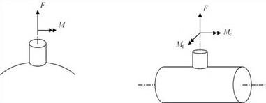
Key: F = Radial force; M = Meridional moment; Mc = Circumferential moment; Ml = Longitudinal moment
Remark
Cn becomes equal to the ratio of shell thickness and nozzle neck thickness.
| Maximum allowable individual flange loads |
|---|
| F = (P_r - P_d) (π/4) G^2 |
| M = (P_r - P_d) (π/16) G^2. C. K_f |
| Auxiliary Value |
| K_f = 1 + [t^2 + (W - d*h)^2/2.6 t^2] |
Table 4: Nozzle Individual flange loads.
Table 4: Nozzle Individual flange loads. The individual permissible forces and moments (which can be applied independently on a nozzle) follow from the application of the procedure described above. Subsequently, the vessel designer append the data of the nozzle load capacity to the requisition or otherwise the manufacturers quotation in a format that corresponds to Table 5, which can consecutively be made available to the pipe stress analyst for further evaluation and judgment. Note that in the case of a nozzle provided with a reinforcing pad, the lowest calculated value must be entered in the Table 5.
- Magnitude of Individual Allowable Nozzle Load Capabilities
- Nozzle / Cylinder Intersection
- Flange Facing
- Nozzle
- F
- [N]
- Ml
- [Nmm]
- Mc
- [Nmm]
- M
- [Nmm]
- N2
- Nozzle / Head /Sphere Intersection
- Flange Facing
- Nozzle
- F
- [N]
- M
- [Nmm]
- M
- [Nmm]
- N1
Table 5: Nozle load capabilities of Nozzle intersection and Flange facing.
- Auxiliary Values
- $C_{11} = (D_o - T)/(2T) = (1600 - 20)/(2 \times 20) = 39.5$
- $C_{21} = (C_{11})^{0.5}/(\pi.T.D_n) = (39.5)^{0.5}/(\pi \times 20 \times 375) = 0.00026674$
- $C_{31} = 4(C_{11})^{0.5}/(\pi.T.D_n^2) = 4(39.5)^{0.5}/(\pi \times 20 \times 375^2) = 0.000002845$
- $C_{41} = (D_n/2T)^{0.5} = (375/2 \times 20)^{0.5} = 3.0619$
Table 6: Determination of auxiliary quantities.
| Design stress | 129.33 MPa | |
|---|---|---|
| $P_{d}$ | Internal design pressure | 3 MPa |
| $P_{r}$ | Rated pressure (ASME B16.5 or ASME B16.47) | 4.085 MPa |
| A | Outside diameter flange | 520 mm |
| B | Inside diameter flange | 305 mm |
| C | Bolt circle diameter | 450.8 mm |
| t | Flange thickness | 49.3 mm |
| G | Effective sealing diameter | 357.3 mm |
| W | Flange width = 0.5 (A - B) | 107.5 mm |
| d_{h}$ | Bolt hole diameter | 31.75 mm |
| $d^{*}_{h}$ | max [$d_{h}(1 - B/1000)$ ; 0.5 $d_{h}$] | 22.066 mm |
Table 7: Determination of Allowable individual flange loads.
| f | Design stress | 129.33 MPa |
| Pd | Internal design pressure | 3 MPa |
| Pr | Rated pressure (ASME B16.5 or ASME B16.47) | 4.085 MPa |
| A | Outside diameter flange | 520 mm |
| B | Inside diameter flange | 305 mm |
| C | Bolt circle diameter | 450.8 mm |
| t | Flange thickness | 49.3 mm |
| G | Effective sealing diameter | 357.3 mm |
| W | Flange width = 0.5 (A - B) | 107.5 mm |
| dh | Bolt hole diameter | 31.75 mm |
| d*h | max[dh(1 - B/1000); 0.5dh] | 22.066 mm |
Table 8: Flange data.
| Design stress | 129.33 MPa | |
|---|---|---|
| $P_{d}$ | Internal design pressure | 3 MPa |
| $P_{r}$ | Rated pressure (ASME B16.5 or ASME B16.47) | 4.085 MPa |
| A | Outside diameter flange | 520 mm |
| B | Inside diameter flange | 305 mm |
| C | Bolt circle diameter | 450.8 mm |
| t | Flange thickness | 49.3 mm |
| G | Effective sealing diameter | 357.3 mm |
| W | Flange width = 0.5 (A - B) | 107.5 mm |
| d_{h}$ | Bolt hole diameter | 31.75 mm |
| $d^{*}_{h}$ | max [$d_{h}(1 - B/1000)$ ; 0.5 $d_{h}$] | 22.066 mm |
Table 7: Determination of Allowable individual flange loads.
- Magnitude of Individual Allowable Nozzle Load Capabilities
- Nozzle / Cylinder Intersection
- Flange Facing
- Nozzle
- F
- [N]
- Ml
- [Nmm]
- Mc
- [Nmm]
- F
- [N]
- N2
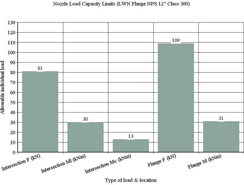
- 80809
- Approx.81 kN
- 30305800
- Approx. 30 kNm
- 12910057
- Approx.13 kNm
- 108789
- Approx.109 kN
Table 9: Nozzle load summary showing calculation results of allowable individual loads.
The pipe stress analyst must demonstrate in its stress report that the piping reactions comply with the Load Interaction Rule for both the vessel nozzle intersection and connecting nozzle flange.
Conclusion
The method provided is aimed for predominantly static
Nomenclature
loaded pressure vessels, whereby the design temperature lies below the creep range for the applied materials. It provides a solution to a vexing pressure vessel - piping interface problem to which vessel - and piping designers often are confronted. Prudent application of the method has proved to be safe and reliable.
| Symbol | Description | Unit | ||||||
|---|---|---|---|---|---|---|---|---|
| F | Force | N | ||||||
| M l | Moment | Nmm | ||||||
| M c | Moment | Nmm | ||||||
| M | Moment | Nmm | ||||||
| f | Design stress | MPa | ||||||
| D o | Outside diameter shell/sphere/spherical part | mm | ||||||
| T | Wall thickness shell/sphere/spherical part | mm | ||||||
| D n | Outside diameter nozzle neck | mm | ||||||
| D pad | Outside diameter reinforcing pad | mm | ||||||
| P d | Internal design pressure | MPa |
| P r | Rated pressure (ASME B16.5 or ASME B16.47) | MPa |
|---|---|---|
| A | Outside diameter flange | mm |
| B | Inside diameter flange | mm |
| C | Bolt circle diameter | mm |
| t | Flange thickness | mm |
| G | Effective sealing diameter | mm |
| W | Flange width = 0.5 (A - B) | mm |
| K f | 'Koves' factor | - |
| d h | Bolt hole diameter | mm |
| d∗h | max [d (1 - B/1000) ; 0.5 d ] h h | mm |
References
-
Rules of pressure vessels, Local Loads, Sheet D 1141 & sheet D 1141-Appendix 1.
-
Dekker CJ, Bos HJ (1997) Nozzles on external loads and internal pressure. Int Journal of Pressure Vessels & Piping 72(1): 1-18.
-
Dekker CJ (1993) External Loads on Nozzles. Int Journal of Pressure Vessels & Piping 53(2): 335-350.
-
Dekker CJ, Brink HJ (2002) External flange loads and ‘Koves’- method. Int Journal Pressure Vessels and Piping 79(2): 145-155.
-
EN 13445-3 (2016) Unfired pressure vessels. Chapter 16, Additional non- pressure loads.
-
PD 5500 (2018) Specification for fusion welded pressure vessels. Annex G - Recommendations for the design of local loads etc. clause G.2.8.2 & G.2.8.3.
-
Rules for pressure vessels, Flange connections, Sheet D 0701.
-
Dekker CJ (1994) Comparison of local load stress calculation methods for nozzles on cylinders. Int Journal of Pressure Vessels & Piping 58(2): 203-213.
-
Dekker CJ, Stikvoort WJ (1997) Pressure stress intensity at nozzles on cylindrical vessels: a comparison of calculation methods. Int Journal of Pressure Vessels & Piping 74(2): 121-128.
- Nigeria’s Vulnerability in the Face of Global Energy Policy
- A Simulation Study of Investigation of Optimum Oil Production Performance by Applying Various Gas Injection Methods in Oil Reservoir
- Characterization of Permo-Triassic Reservoirs through Thermal Maturity Assessment of Westphalian Source Rocks in the Cheshire Basin
- Influence of Microwax on the Rheological and Thermal Behaviour of a Wax Crude Oil
- Real-Time Monitoring and Performance Optimization of Steam Injection in Heavy Oil Reservoirs Using Fiber Optic Sensing and Integrated Predictive Simulation Models
- Rapid On-Site Determination of the Total Petroleum Hydrocarbon Content of Soils by Handheld Fourier Transform Near-Infrared Spectroscopy: Development of a Global, Site- and Scanner- Independent Calibration Model