Relevant Information on Oil and Gas Casing Design
Casing design is an important task in oil and gas well design. Casing design involves evaluation of the factors that con tribute to the failure of the casing and proper se lection of the most suitable casing grades and weights that are both safe and economical for a specific job operation. A good knowledge of stress calculation is very essential in casing design. During casing design, various modes of casing failure must be identified and carefully handled such that the selected casing within a well segment is able to withstand all the failure modes. A safety margin, (also known as factor of safety) is always provided in casing de sign to allow for the future variations in the casing strength, loading and other unknown forces which may be encountered. This paper provides key information, education, relevant and technical details on casing design for oil and gas well.
Introduction
Oil casing is the pipe wall, used to support the oil and gas, to ensure normal operation of the post-completion wells at the drilling process [1]. Design of casing string calls for knowledge of the operating conditions imposed on the casing as well as the concepts related to pipe properties [2]. Casing serves numerous purposes in oil and gas wells. Safe and economical sizing of casing is therefore an important task in oil and gas well design. Casing situation requires that the formation pressure at various sections of the well should be determined [2]. Casing prevents formation from interfering into the borehole activities. The first step towards the casing design procedure is the initial well data [3]. Therefore, incorrect initial data could cause incorrect casing design.
If casings are not sized correctly, then such casings are prone to failure at their early stage of operation.
Tensile, compressive, bending, tensional stress jointly affect on the tube, which makes the casing itself, need the higher quality requirements [1]. Casing wear in the oil and gas industry is recorded on a world basis [4]. Rotation of drill-pipe during the drilling process creates significant contact forces that result in the reduction of casing wall thickness [4]. Thickness reduction of the casing wall weakens the burst and collapse strength of casing. This is one of the causes of failure in casing even before oil and gas production. Casing can also fail by bursting. This occurs when the applied burst stress on the casing during the operational conditions of the well exceeds the casing burst strength. The burst stress tends to exert force on the inside walls of the casing. Casing can also fail by collapse. The collapse of casing and tubing may lead to the loss of a well [5]. Collapse stress on casing act on the outer walls of the casing and increases with the depth of the casing. Collapse is a complex phenomenon with a great many factors and parameters that influence its effect [5].
The collapse phenomenon is commonly attributed to suspected quality problems in the pipe. However, studies show there are a set of causative factors, such as: wear on casing, wear due to buckling, increased external pressure due to temperature, improper depressurization, geostatic loads (overburden) due to plastic formations and tectonic activity [5].
Because of the various modes of failure of the oil and gas well casing, it therefore becomes necessary to design casing sufficiently with recommended factors of safety. The design standards recommend various factors of safety for the design of casing against different modes of failure. There are different types of casing. Casing, according to usage, can be divided into: catheter, surface casing, intermediate casing and production casing [1]. According to (Petrowiki) [6], to design a casing string, one must have knowledge of:
- Purpose of the well
- Geological cross section
- Available casing and bit sizes Cementing and drilling practices Rig performance
- Safety and environmental regulations The engineer responsible for developing the well plan and casing design is faced with a number of tasks that can be briefly characterized.
While the intention is to provide reliable well construction at a minimum cost, at times failures occur. Most documented failures occur because the pipe was exposed to loads for which it was not designed. These failures are called “off-design” failures. “On-design” failures are rather rare. This implies that casing-design practices are mostly conservative. Many failures occur at connections. This implies that either field makeup practices are not adequate, or the connection design basis is not consistent with the pipe-body design basis.
Casing Design Criteria
Casing damage is always the thorny problem in the process of oil field development, so the research of its mechanism and influencing factors plays a great important role in ensuring casing security [7]. In practice, casing is economically designed against buckling, collapse, tension and bi-axial loads.
Casing Design for Collapse
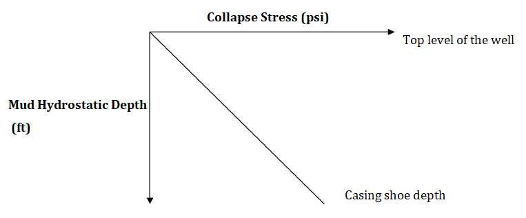
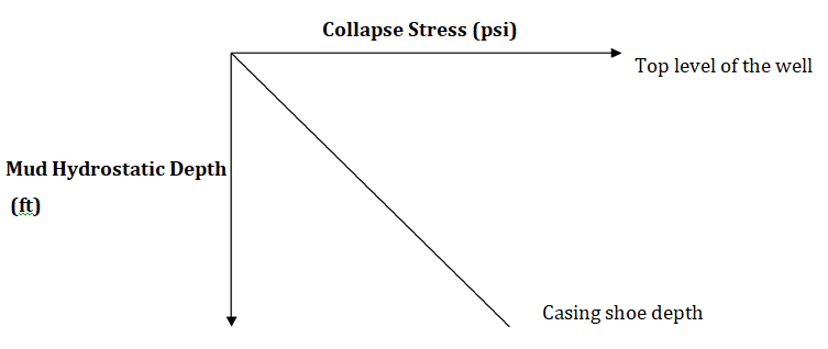
Casing is usually designed against worst collapse conditions. The worst collapse conditions happen when the casing inner portion is assumed to be empty and the annulus completely filled with the drilling mud. Casing collapse stress increases with the mud hydrostatic depth. The casing is usually filled with mud weight. At the top- most segment of the casing where the depth is approximately zero, the collapse stress is zero Collapse Stress = 0.0152ƍh (psi) ---------------- Equation 1 Where: ƍ = mud weight (pound per gallon, ppg) h = mud hydrostatic depth (ft) From the Equation 1, the profile of the collapse stress is presented below:
Copyright© Olanrewaju AO.
Olanrewaju AO. Relevant Information on Oil and Gas Casing Design. Pet Petro Chem Eng J 2018, 2(4): 000179.
Casing Design for Burst
Casing is subjected to burst stress. In practice, it is safer to design the casing for unlimited condition. Under unlimited casing design against burst, it is assumed that the invading fluid from the completely fills the casing from the bottom to the top. At the top of the hole, the external pressure due to mud is zero and the internal pressure must be supported entirely by casing body. Burst is the highest at the top and least at the casing shoe. The profile
Casing Design for Tension
Oil and gas well casings are designed against failure by tension. Tension stress on a casing is due to own-weight of the casing and the weight of the other casings supported. The topmost casing segment in the well carries the highest tension stress while the last bottom casing in the well carries the least tension stress. Since the casing is always submerged in the drilling mud, the effect of buoyancy on the casing is therefore considered in the casing design [8]. Buoyancy Factor, BF can be expressed as BF = 1 − ƥmud/ƥsteel Where ƥmud = mud weight (in pounds per gallon, ppg) ƥsteel = steel weight (in pounds per gallon, ppg)
Casing Design Check for Biaxial Loads
Under tensile stress, the casing thickness reduces and the casing collapse strength also reduces. The remaining collapse strength of the casing should be determined to ensure that casing selected can withstand the collapse stress at the maximum hydrostatic depth of the casing. The table below shows the remaining collapse strength of the casing as a function of tensile ratio.
| Tensile Ratio =Weight carried/Yield Strength | Remaining Collapse Strength % |
|---|---|
| 0 | 100 |
| 0.1 | 94.5 |
| 0.2 | 88.5 |
| 0.3 | 81.3 |
| 0.4 | 76 |
| 0.5 | 65 |
| 0.6 | 65 |
| 0.7 | 44.5 |
Table 1: Remaining Collapse Strength (Biaxial Load Check).
Types of Casing
Conductor Casing
- Run from surface to some shallow depth to protect near surface unconsolidated
- formation
- Provide a circulation for the drilling mud to protect foundation of the platform
- May be connecting of BOP or cut at surface or diverter connection
- Sizes from 18 5/8 in to 20 in
Surface Casing (13 3/8 in.)
- Run to prevent caving of week formation encountered at shallow depths
- Should be set in competent rock like limestone: to ensure that the formation will not fractured at the casing shoe by high mud weight used later in the next hole
- Protect against shallow blow-out, thus BOPs are connected to top
Intermediate Casing (9 5/8 in.)
1. Usually set in the transition zone below or above pressured formation (salt and/or caving shale) 2. Need good cementing to prevent communication behind the casing between zones; multistage cementing may be used for long strings
Production Casing (7 in.)
- Isolate production zones
- Provide reservoir fluid control
- Permit selective production in multi zones production Copyright© Olanrewaju AO.
Olanrewaju AO. Relevant Information on Oil and Gas Casing Design. Pet Petro Chem Eng J 2018, 2(4): 000179.
Liner Casing
1. A string of casing that does not reach to the surface 2. Hang on the intermediate casing, by use of suitable packer and slips called liner hanger
Casing Grades
According to the strength of the steel casings, they can be divided into different steel grades, namely J55, K55, N80, L80, C90, T95, P110, Q125, V150 and other. Under well conditions, different casing steel grades have different strengths. In corrosive environments, casing itself also requires corrosion resistance. In place of complex geological conditions, casings also require anti- collapse properties. In design, different casing steel grades are set at different depths of the well. Different casing grades have different collapse strengths, burst strengths and tensile strengths. It is therefore very important to set a casing at depth, where it is capable to withstand collapse stress, burst stress and tensile stress throughout its length.
Design Factors of Safety (F.O.S)
Casings are usually designed with allowance for variability in material strength, human design error, and unforeseen circumstances on the field.
Collapse Load
Collapse is first calculated for the surface casing, collapse at the surface will be zero. Collapse at the casing shoe = Mud gradient * Depth of casing shoe Hence, design collapse load will be = Collapse at casing shoe * F.O.S F.O.S for collapse is generally 1.1-1.25
Burst Load
The burst load at casing shoe = internal pressure – external pressure Where: Internal pressure = Fracture gradient * Depth of casing shoe External pressure = Fresh water gradient * Depth of casing shoe Design Burst at casing shoe = F.O.S * Burst load at casing shoe F.O.S for burst load is generally 1.2-1.8 Burst load at surface is also calculated using similar procedure.
Axial Load
Axial load is to be calculated separately for each section of casing. The factor of safety for axial loads seems higher than other load cases due operational activities such over- pull of the casing string during sticking. The acceptable factor of safety for axial load/tension load is 1.6-1.8. Therefore, Design Axial Load = Axial load * 1.8 (F.O.S). Good casing design should incorporate all these factors to provide sufficient allowance against different forms of casing failures.
Essential Data for Casing Design
Some data are required for casing design. These data could be assumed based on experience, existing wells at the location, drilling manuals and casing property tables. The data could be grouped into 4 categories based on the type of data. The data can be grouped into:
- Formation pressure at the depth of next hole section data
- Fracture gradient data
- Mud program data
- Available casing data The following highlights the basic data required for the casing design.
References
-
Hua Tong, Xiao-Hong Tang (2016) Oil Casing Introduction. International Journal of Science and Research (IJSR) 5(6): 696-698.
-
Edaigbini PI, Maikobi AA (2015) Casing Design for High Pressure/High Temperature Wells. Innovative Systems Design and Engineering 6(3): 9-25. Copyright© Olanrewaju AO. Olanrewaju AO. Relevant Information on Oil and Gas Casing Design. Pet Petro Chem Eng J 2018, 2(4): 000179.
-
Thattil MS (2017) Casing Design for Casing/Liner while Drilling. International Research Journal of Engineering and Technology (IRJET) 4(7): 1-3.
-
Zheng Shen, Frederick E Beck, Kegang Ling (2014) The Mechanism of Wellbore Weakening in Worn Casing-Cement-Formation System. Journal of Petroleum Engineering 2014: 8.
-
Asadi A, Parhizgar N, Momeni E (2011) Prediction of Collapse in a Casing and Tubing: with Case Study of Iran. Australian Journal of Basic and Applied Sciences 5(11): 831-840.
-
Petrowiki (2015) Casing design.
-
Jianjun Liu, Xianbin Yu (2012) Stress Analysis on the Combination of Casing-Cement Ring -Surrounding Rock Considering Fluid-Solid Coupling. Electronic Journal of Geotechnical Engineering 1863-1873.
-
Liping Guo, Xu Chen, Xiaoyang Yu, Shuang Shi, Yu Wang (2015) Research on Casing Damage Based on Effect of Water Injection Pressure. Open Journal of Fluid Dynamics 5: 208-214. Copyright© Olanrewaju AO. Olanrewaju AO. Relevant Information on Oil and Gas Casing Design. Pet Petro Chem Eng J 2018, 2(4): 000179.
- Nigeria’s Vulnerability in the Face of Global Energy Policy
- A Simulation Study of Investigation of Optimum Oil Production Performance by Applying Various Gas Injection Methods in Oil Reservoir
- Characterization of Permo-Triassic Reservoirs through Thermal Maturity Assessment of Westphalian Source Rocks in the Cheshire Basin
- Influence of Microwax on the Rheological and Thermal Behaviour of a Wax Crude Oil
- Real-Time Monitoring and Performance Optimization of Steam Injection in Heavy Oil Reservoirs Using Fiber Optic Sensing and Integrated Predictive Simulation Models
- Rapid On-Site Determination of the Total Petroleum Hydrocarbon Content of Soils by Handheld Fourier Transform Near-Infrared Spectroscopy: Development of a Global, Site- and Scanner- Independent Calibration Model