Depulsators before Oil & Gas Field Plants and Equations for Calculating the Main Element of Depulsators, Venturi Nozzles
Pipe depulsators are preliminary gas separation devices (PGSD). Professor E.P. Zaporozhets, the author, developed alternative depulsators – Autonomous Venturi nozzles (AVN) and depulsators-distributors of flows (FDD) with a Venturi nozzle (VN) at the entrance. There is a new method of selecting depulsators of new generation on the basis of Venturi nozzle. This method allows selection of Venturi nozzle neck diameter that does not allow overflow of separators. The main size of Venturi nozzle is the diameter (reduced diameter) of the Venturi nozzle critical section. The article presents refined system of equations to determine VN geometric parameters and equation to calculate the area of Venturi nozzle critical section. Speed of liquid and gas in critical section should be no more than 20 m/sec, 320 m/sec respectively. AVN depulsators can be installed a few kilometres from the plant. AVN depulsators are more compact, PGSD are smaller in size, length and height. Depulsators of any type are installed before oil&gas plants, mainly before inlet separators. Depulsators are installed in Western Siberia and Krasnodar region and are recommended at marine oil & gas platforms.
Review with Recommendations on Application and Calculations
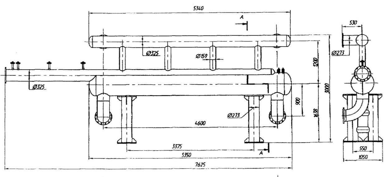
At the output of the pipeline, that transport gas, oil and water to the oil & gas plants for inhibition of liquid (watered down oil) the following depulsators are used in Depulsators before Oil & Gas Field Plants and Equations for Calculating the Main Element of Depulsators, Venturi Nozzles Milshteyn LM [1]: preliminary gas separation device (PGSD), Figure 1, autonomous Venturi nozzles (AVN), Figure 2, flow distributing depulsators (FDD) with Venturi nozzle (VN) at the entrance, Figure 3.
Pet Petro Chem Eng J
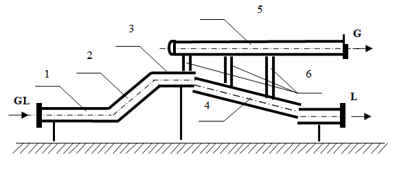
![Figure 2: Venturi Nozzle (VN): 1. Entrance part before confusor; 2. Confusor; 3. Critical section (neck); 4. Diffusor; 5. Exit part after diffusor. The geometric parameters of Venturi nozzle are determined by the system of equations [2]:](/fulltextimages/4632/fig_2.png)
$$ \beta = 5 ^ {o} \dots 1 0 ^ {o}; S _ {c o n} = 0, 5 \left(D _ {1} - D _ {c}\right) / c t g ^ {\alpha} / _ {2}; S _ {d i f} = 0, 5 \left(D _ {2} - D _ {c}\right) / c t g ^ {\beta} / _ {2}; S _ {t o t a l} = S _ {1} + S _ {c o n} + S _ {c} + S _ {d i f} + S _ {2}. $$ Diameters: entrance part to the nozzle confusor (D1), nozzle critical section (Dc), the part after nozzle diffusor (D2); Angles: narrowing of confusor (α), widening of diffusor ( β);
Milshteyn LM. Depulsators before Oil & Gas Field Plants and Equations for Calculating the Main Element of Depulsators, Venturi Nozzles. Pet Petro Chem Eng J 2019, 3(4): 000208.
Lengths: of the entrance part before confusor входного (S1), part after diffusor (S2), neck of the nozzle (Sc), confusor (Scon), diffusor (Sdif), the total length of Venturi nozzle (Stotal).
Copyright© Milshteyn LM.
Depulsators of all types are placed in front of oil & gas plants, mainly in front of inlet separators. AVN can be installed in a few kilometers away from the plants. For example, depulsators ACV is located a few kilometers from Yuzhno-Balyk gas processing plant (YB GPP). AVN depulsators are installed before the entrance separators and heat exchangers, which are installed before them and have one branch pipe for the entry of mixture. PGSD and FDD depulsators are installed before the entrance separators with separate branch pipes for the entry of gas and liquid [1]. Depulsators of all types are installed before the following separators:
Oil&gas separators (OGS) for separation of oil-gas mixture; Vertical three-phase separators (VTS) for separation of gas- oil-solids mixture; OGS with water discharge (OGSW) for separation of gas-oil- water mixture. The area of critical section VN is determined by the formula [2]: 0.2 с el F F ≤ (3), Milshteyn LM. Depulsators before Oil & Gas Field Plants and Equations for Calculating the Main Element of Depulsators, Venturi Nozzles. Pet Petro Chem Eng J 2019, 3(4): 000208.
where Fc, Fel is the area of VN critical section and through- passage section of branch pipe or pipeline for the exit of liquid respectively, if the area of the last is less than that of the branch pipe.
The speed of oil gas through the VN neck should be less than the speed of sound of oil gases Wgsv = 330…430 m/sec, otherwise the sound mode of the flow begins Milshteyn LM [1]. The Venturi nozzle has to be checked by the gas, so that the maximum allowed speed of gas in the neck (Wgc) were less than the speed of sound – Wgc = 320 m/sec. Estimated maximum speed of liquid in critical section of Venturi nozzle is Wlc = 20 m/sec.
The area of VN neck is limited by the expenditure of the liquid (Ql) [1, 2]: Fc ≥ Ql/Wlc= 0.05Ql (4), where Ql, Wlc is expenditure of the liquid, m/sec and speed of liquid in the VN neck, m3/sec, respectively.
Consider the work of Venturi nozzle in FDD depulsators of Slavyanski separation plant (SSP) and KBPS before the OGS and VTS oil & gas separators respectively, Table 1. There are two calculations of VN parameters: 1) with depulsators with Venturi nozzles according to relations (2); 2) with depulsators with VN, subject to formula (3) and (4).
Copyright© Milshteyn LM.
| Parameters | F | DD SSP and two OG | S | FDD KBPS and two VTS | ||||
|---|---|---|---|---|---|---|---|---|
| Projected working pressure at the plant entrance, MPa abs. | 2.2 | 0.4 | ||||||
| Capacity of two separators for liquid, m3/sec (m3/h) | 0.05556 (200) | 0.00833 (30) | ||||||
| Calculations 1, Parameters of Separators with FDD Equipped with VN According to Formula (1) or (2) | ||||||||
| The inner diameter of the inlet area into the nozzle confuser, D , mm 1 | 309 | 75 | ||||||
| Reduced diameter of Venturi nozzle critical section, D, mm с | 142 | 30 | ||||||
| Ratio (1), D 12/D c2 ((2), D 1/D c) and assessment of the equation | 4.7 (2.2) > 2.0 | 6.3 (2.5) > 2.0 | ||||||
| Speed in exit branch pipes of liquid from separators, m/sec | 9.0* | 0.9 | ||||||
| Relation of actual expenditure of liquid to critical expenditure | 2.2* | 0.2 | ||||||
| Calculations 2, Parameters of Separators with FDD Equipped with VN, Subject to Formula (3) and (4) | ||||||||
| Selected diameter of Venturi nozzle critical section, mm | 80 | 40 | ||||||
| Ratio (1), D 12/D c2 ((2), D 1/D c) and assessment of the equation | 14,9 (3,9) >> 2,0 | 3,5 (1,9) > < 2,0 | ||||||
| Speed of liquid in exit branch pipes from separators, m/sec | 2.8 | 1.6 | ||||||
| Relation of actual expenditure of liquid to critical expenditure | 0.7 | 0.4 |
Table 1: Calculations of parameters for VN depulsators FDD SSP and FDD KBPS with two separators. Note: * The parameters exceed ma
| Parameters of Depulsators | PGSD | FDD | AVN | ||||||||
|---|---|---|---|---|---|---|---|---|---|---|---|
| Capacity: by gas under the projected working pressure, 0.4 MPa abs., m3/h by liquid, m3/h | 29 375 96.7 | ||||||||||
| Length of depulsator, m | 25 | 7.6 | 1.4 | ||||||||
| Height of depulsators from the ground level (“zero” point), m | 6.6 | 3.0 | 0.4 | ||||||||
| Size (volume) of depulsator, m3 | 115.5 | 23.9 | 0.2 | ||||||||
| Height of elevation of liquid over the supplying pipeline, m | 7.4 | 2.8 | 2.8 |
Table 2: Size of depulsators installed before two OGSW plant KBPS.
Conclusions
1. There is a new method of selecting depulsators of new generation on the basis of Venturi nozzle, in particular, for the entrance oil & gas separators OGS, VTS, OGSW, and heat exchangers installed before them. This Milshteyn LM. Depulsators before Oil & Gas Field Plants and Equations for Calculating the Main Element of Depulsators, Venturi Nozzles. Pet Petro Chem Eng J 2019, 3(4): 000208.
(reduced diameter) of the Venturi nozzle critical section. The article presents refined system of equations to determine VN geometric parameters and equation to calculate the area of Venturi nozzle critical section. Speed of liquid and gas in critical section Copyright© Milshteyn LM.
should be no more than 20 m/sec и 320 m/sec respectively. 3. Depulsators of any type are installed before oil&gas plants, mainly before inlet separators OGS, VTS, OGSW, where AVN can be installed a few kilometres from the plant. AVN depulsators are more compact, PGSD are smaller in size, length and height. 4. Depulsators AVN and FDD are installed in Western Siberia and Krasnodar region and are recommended at marine oil&gas platforms.
References
-
Milshteyn LM (2017) Oil & Gas Field Separation Technique. 2nd (Edn.), Open Science Publishing, Raleigh, North Carolina, USA, pp: 211.
-
Milshteyn LM (2018) Determination of Venturi Nozzles Dimensions of Pulsation Bottles Installed in Milshteyn LM. Depulsators before Oil & Gas Field Plants and Equations for Calculating the Main Element of Depulsators, Venturi Nozzles. Pet Petro Chem Eng J 2019, 3(4): 000208. front of Input Oil and Gas Separators. Equipment and Technologies for Oil and Gas Complex 2: 39-43.
-
Zaporozhets EP (2009) Principal patterns and methods of calculations for equipment and devices for gathering of large quantities of liquid from gas pipelines. UK Russ Gas Engineering, pp: 71.
-
Milshteyn L (2012) Modernization of oil and gas field separation. _In_: Lambert L (Ed.), Development of separation equipment and devices of new generation. Academic Publishing, Saarbrucken, Deuschland, pp: 124.
-
Zaporozhets EP, Antoniadi DG, Zibert GK (2012) Regular processes and equipment in technologies of collection, preparation and processing of oil and natural gases. Kuban state technological university, Krasnodar: Publishing house, pp: 620. Copyright© Milshteyn LM.
- Nigeria’s Vulnerability in the Face of Global Energy Policy
- A Simulation Study of Investigation of Optimum Oil Production Performance by Applying Various Gas Injection Methods in Oil Reservoir
- Characterization of Permo-Triassic Reservoirs through Thermal Maturity Assessment of Westphalian Source Rocks in the Cheshire Basin
- Influence of Microwax on the Rheological and Thermal Behaviour of a Wax Crude Oil
- Real-Time Monitoring and Performance Optimization of Steam Injection in Heavy Oil Reservoirs Using Fiber Optic Sensing and Integrated Predictive Simulation Models
- Rapid On-Site Determination of the Total Petroleum Hydrocarbon Content of Soils by Handheld Fourier Transform Near-Infrared Spectroscopy: Development of a Global, Site- and Scanner- Independent Calibration Model