Development of Technologies and Technical Means for the Construction of Wells Intended for the Production of High Viscosity Oils
The development of technologies and technical means of well structures intended for the production of high-viscosity oils is an urgent problem in the oil and gas industry. The design of well structures is determined by geological factors. The well design should ensure trouble-free construction of a sealed space of a stable channel between the fluid-saturated layers and the earth's surface.
Construction of Wells
Construction of wells is shown in Figures 1 and 2 [1].
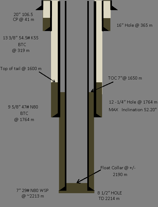
Construction of wells is shown in Figure 2.
Well Drilling
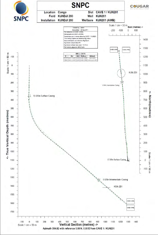
Rig preparation went as planned and the target date of being reading by 1st September was realized. The Commencement of the 16” section - make up 16” Bit and BHA was delayed by 14 hours as compared to the plan which was to start at midnight of the first day. The top hole section progressed very smoothly with only minor periods of NPT. Considering the rig & rig crew had been idle for a long period prior to the commencement of the project it was an impressive start to the operation.
Drilling 16” hole versus 17 ½” hole didn’t end up being productive since fewer cuttings were generated but lost time and unable to run the 13 3/8 casing past 319 m (stuck depth) resulted in a weak shoe and leak off occurred earlier than program expectation. This resulted in loss of oil base mud in the subsequent 12 ¼” section and significantly raised the end cost for the section mud invoice [2].
There is an argument that this may have been partly due to the Pendulum BHA design. However if it is decided to continue with 16” hole then as a precaution a Near Bit stabilizer and one string stabilizer are recommended. Directional drilling motor failed at 1672m. A backup motor and MWD had to be run in hole to drill ahead to TD at 1764m.
Install a Huet or pumping sub in the directional drilling BHA. If the mud motor fails, a ball can be dropped and circulation above mud motor established through the ports. When mud motors fail 95% of the time the stator rubber clogs the bit nozzles and circulation becomes impossible, without circulation pulling out of hole with all the cuttings uncirculated. A stuck pipe scenario can occur and side track may have to be performed if string is permanently stuck. This occurred on Kun 201 and we were fortunate to get out of the hole without any circulation. These subs are also used for pumping of Loss circulation materials in high concentrations since there is a limitation to particles size and amount being pumped through the MWD and mud motor, PDC nozzles [3].
Drilling Fluids
During the drilling operation, the troublesome anhydride formation reacted with diluted PHB to excessively create foam that led to some perturbations of the viscosity which was controlled by calcium precipitant; also LCM of various sizes and fluid loss controller were used to maintain the required parameters.
During this well drilling, screens mesh was limited at 120 meshes, so only 0.30 m was noted in Active tanks. Derrick men were forbidden to open shaker by-pass and this was enforced by Mud man on site. A lot of base oil was consumed in trying to keep the mud weight in check since the Verti-G centrifuge equipment was not functioning correctly, also noted on Kun 201 but not as dramatically. A dedicated base oil wash gun is still required at shakers or installs a fourth shaker since three can’t handle the flow rates required for the larger mud motors being used. The flow rate is slowed sometimes to lowest possible rate to compensate for the weakness noted at shakers level. This is detrimental to performance drilling since the motor speed is reduced to slowest rpm [4]. Pore pressure and fracture gradient vs depth for MW and ECD is shown in Figure 3.
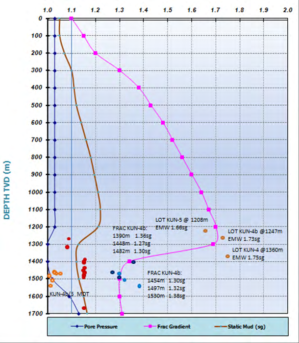
Estimated profiles have been generated taking into account all reports from offset wells (mainly daily drilling reports and end of well reports), leak off tests, Frac Data, pressure points (MDT) and log interpretation.
Conclusion and Recommendation
Lost time due to poor drilling practice, such as racking back in derrick particular crossovers that are required in another BHA, then much time is lost recovering the crossover, sometimes even layed out unbroken on drill floor or on location. Burying collars and other required tubulars in the derrick resulting in time spent moving tubulars from one side of derrick to other side. This also occurred because crews don’t communicate at change over or no written instructions given to drillers, tool pushers on forward plan. Written instructions must be in place for upcoming 24 hours phase so planning can be made ahead of time and equipment is in place and ready.
BOP reliability is improved and substantial time savings can be made by making up and testing the BOPs on a purposely designed BOP Test Stump during the drilling phase. Using this method the BOPS can be 90% tested so that once the casing has been cemented and the wellhead installed the BOPs can be installed over the wellhead and only the remaining 10% nipple up and Pressure tests carried out.
The BOP had many problems while testing which could have been avoided with a stump testing facility. Leaking ram rubbers, crossed lines and lack of labeling on control lines was the main contributing factor to this lost time. This has now been rectified and lines are labeled to avoid a repeat.
The rig had very insufficient solids control equipment. The shakers were only capable of handling 80 mesh screens and aside from a 14m3 settling pit; all that was available was a desilter on top of a vibrating screen.
The losses problems during 12 ¼’’ section was a cause to the non-operating of the solids control equipments so the mud density kept on increasing until some fractures allowed mud invasion in the formation but various fluid loss controllers were added to active system as drilling progressed to break it down.
For future wells it is recommended that a dedicated wash gun able to operate with base oil be stationed at the shakers for cleaning shaker screens. Also it is very important to have access to a dedicated centrifuge at all times while drilling with Oil Base Mud.
The work on the removal of the conductor went as planned as did the cutting of the 13-3/8” casing to correct height for wellhead installation. There was however some unrecorded NPT related to the correct procedures for dressing off and welding on A section. The wellhead installation on the 13- 3/8” casing is a critical operation as it is installed for the life of the well. Correctly trained and certified welders are essential for this operation.
References
-
Ovchinnikov VP, Rozhkova OV, Ovchinnikov PV, Shemelina ON (2019) High Viscosity Oil Development Technology. International Journal of Petroleum Technology 6: 35-40.
-
Paveleva ON, Parshukova LA, Ovchinnikov VP, Paveleva YuN (2020) Changes in filtration properties in reservoir rocks during drilling. Subsurface use of the XXI century 83(1): 64-69.
-
Paveleva ON, Karnaukhov ML (2017) Studies of horizontal gas condensate wells. Proceedings of higher educational institutions, Oil and gas 3: 56-61.
-
Shemelina ON (2020) Development of a drilling mud formulation. Proceedings of the XXIV International Symposium named after Academician MA Usov of students and young scientists dedicated to the 75th anniversary of Victory in the Great Patriotic War “Problems of geology and subsoil development”, Tomsk, Russia, pp: 439-440.
- Nigeria’s Vulnerability in the Face of Global Energy Policy
- A Simulation Study of Investigation of Optimum Oil Production Performance by Applying Various Gas Injection Methods in Oil Reservoir
- Characterization of Permo-Triassic Reservoirs through Thermal Maturity Assessment of Westphalian Source Rocks in the Cheshire Basin
- Influence of Microwax on the Rheological and Thermal Behaviour of a Wax Crude Oil
- Real-Time Monitoring and Performance Optimization of Steam Injection in Heavy Oil Reservoirs Using Fiber Optic Sensing and Integrated Predictive Simulation Models
- Rapid On-Site Determination of the Total Petroleum Hydrocarbon Content of Soils by Handheld Fourier Transform Near-Infrared Spectroscopy: Development of a Global, Site- and Scanner- Independent Calibration Model