Implementation Challenges of Extended Reach Drilling and Hydraulic Fracturing Operations in Unconventional Reservoirs
The petroleum industry faces a lot of challenges in producing hydrocarbons. These challenges became significant with the discovery of unconventional reservoirs. This called for new advanced technologies to be developed. Extended Reach Drilling (ERD) and Hydraulic Fracturing (HF) are two methods that were successfully implemented in different wells around the world. ERD has been used in numerous drilling operations where the reservoir is surrounded by troublesome formations, hence sidetracking is necessary. Hydraulic fracturing is used in the development of many unconventional wells, including shale gas reservoirs. However, these methods still face a lot of challenges during implementation, which can affect the success of the drilling and well completion design. This article discusses the main design considerations for implementing ERD and Hydraulic fracturing in an unconventional reservoir. It also covers the main challenges that should be accounted for while preparing the drilling and well stimulation design to improve the production efficiency. It includes the impact of stress shadows, frac hits, well spacing, casing design, and other factors on the overall success of the process.
Introduction
Major economies have depended on conventional oil and gas supplies derived from vast sedimentary reserves for almost a century. Unconventional natural gas and oil resources have become increasingly important as conventional stocks decline in tandem with rising energy demands. In comparison to traditional hydrocarbons, producing these resources necessitates a fundamental shift in drilling and production [1]. We have depended on conventional oil and gas supplies derived from vast sedimentary reserves for almost a century. Unconventional natural gas and oil resources have become increasingly important as conventional stocks decline in tandem with rising energy demands.
In comparison to traditional hydrocarbons, producing these resources necessitates a fundamental shift in drilling and production technologies [2]. Unconventional reservoirs have a significant difference in their chemical and physical characteristics compared to conventional reservoirs. Gas hydrates, heavy-oil sandstones, oil shale formations, shale gas, and tight-gas sandstones are examples of unconventional reservoirs that require stimulation procedures to increase the economic recovery rates [3].
The oil and gas industry has been progressively migrating to drilling horizontal and deviated wells with the advent of supporting technology such as logging- while-drilling (LWD) devices Zhang, et al. [4] and rotary- steerable drilling rigs [5], notably in unconventional and offshore applications. The benefits of moving from vertical to horizontal and deviated wells include increased reservoir exposure and increased reservoir connections. Horizontal drilling needs a much smaller number of wells than vertical drilling. In general, one horizontal well may produce the same amount of oil as numerous vertical wells combined. This minimizes the amount of surface infrastructure needed and saves a lot of money, particularly for unconventional and offshore projects. Extended Reach Drilling (ERD) is a type of directional drilling with longer horizontal sections [6]. To achieve optimum production and drainage capabilities, ERD attempts to produce a larger exposure area from a single surface position and keep the well in touch with the reservoir for a longer distance.
ERD technology is among the most frequent ways to access reservoir reserves cost-effectively, including for reserves that were formerly unreachable. Furthermore, ERD can help exploration and production facilities possess reduced environmental footprints. For these advantages, service providers are investing in this technology to expand the ERD’s boundaries. This technology was employed in several areas, including the Sakhalin field in Russia, where the drilled horizontal section reached a measured depth over 12 km [7]. Hydraulic fracturing (HF) is a widely used technique to increase the productivity of wells, especially those with originally extremely low permeability. It dates to the late 1940s but was not utilized on a large scale until the exploration of unconventional resources e.g., shale gas reservoirs, coal bed methane, and others [8]. It can overcome some problems associated with formation damage and provide a permeable pathway leading to an increase in productivity [9].
The main aim of applying hydraulic fracturing is to create new fractures in the reservoir that leads to an increase in permeability and hence a pathway for hydrocarbons to flow into the surface. Perforations are executed within the pay zone to create direct communication between the well and reservoir. A fracture propagates in the direction parallel to the minimum principal stress when the pressure exceeds the fracture opening pressure. Hydraulic fracturing can be divided into two stages, the pad and slurry stages [10]. The pad stage includes injecting fracturing fluids at high flow rates to break down the formation. The slurry stage includes pumping proppants along with the fracturing fluid into the well to keep the fracture open. When creating a well stimulation design, several factors must be addressed, including the cluster spacing, fluid design, proppant concentration, proppant size and type, and stage duration. To obtain high recovery factors, the procedure should be customized for each unconventional reservoir based on its subsurface and mechanical qualities. Well spacing is an essential factor to consider in the design. The overall number of wells required for a project is determined by well spacing. The gap between wells draws nearer as additional wells are drilled and fractured. This might create interference between adjacent wells, resulting in a decrease in the total projected recovery [11]. It is evident that both Extended Reach Drilling and Hydraulic Fracturing go side by side to produce most of the unconventional reservoirs. However, these operations face a lot of challenges that many might not be familiar with. In this article, the main design procedures for both the ERD and HF are discussed. Additionally, some critical challenges that can be encountered during the implementation stage are covered. This includes, but not limited to, frac hits, stress shadows, well spacing, torque and drag forces, and other factors.
Unconventional Reservoir Development Design
Extended Reach Drilling (ERD)
ERD wells are known to have significant inclination angles that are around 90°, and extremely long horizontal displacements that exceed twice the True Vertical Depth (TVD) of the well. This results in significantly larger drag, torque, and hook loads compared to conventional wells. To create an efficient ERD design, several parameters should be considered that include the drill string, casing, and hydraulics design [12]. These designs are briefly described as follows:
Drill String Design
The drill string refers to a column or stack of equipment used during drilling. It provides a pathway for fluids and mud to reach the subsurface while transmitting the required torque to bottomhole equipment. This drill string includes drill pipes, drill collars, and drill bits [13]. During drilling, the drill string encounters escalated frictional forces that may halt its movement and prevent it from successfully reaching its target. This phenomenon is more common when pulling out of the hole or slacking-off the drill string. To prevent these problems and improve the efficiency of our drilling operation, some preliminary factors should be considered [6]. Firstly, it is important to reduce the number of tripping-in and tripping-out of the hole. This would decrease the overall contact between the drill string and the borehole wall, which reduces the possibility of getting stuck equipment. Secondly, the drill string design should minimize the maximum handled load. This reduces the overall requirements of our drilling rig and hence can significantly lower the drilling costs by renting a cheaper rig. Thirdly, to further reduce the drilling cost, it is necessary to minimize the overall length of the Heavy Weight Drill Pipe. These factors greatly depend on the field conditions and the availability of equipment in an area. Therefore, they should be uniquely adjusted for every ERD design.
Four main parameters greatly impact the efficiency of the drill string design. These parameters are Rudi Rubiandini [12]:
- Neutral point: This refers to the location on the drill string where the forces acting on the equipment are neither in compression nor tension.
- Hook load force: This refers to all the forces acting on the hook at the surface because of the weight of the drill string, drill collars, drill bits, and other subsurface equipment.
- Torque force: This refers to the rotational force that exists between the formation wall and the drill string.
- Axial force: This includes the different forces acting on the axial direction of the drill string.
Casing Design
The casing configuration in ERD wells is harder than other ordinary wells. One of the primary issues that might occur is that the rig’s capabilities may be insufficient owing to the significant casing loads that would be experienced during drilling, all of which must be overseen simultaneously. Furthermore, because the enormous frictional force exceeds the available weight force that the casing can manage, establishing the setting depth of the casing seems to be almost unattainable. To solve these issues and improve casing design, one of four different approaches can be used as shown in Figure 1: conventional method, tie-back method, casing floatation method, and partial-floatation method [12]. The technique of installation to be used is determined by the field conditions. • Conventional method: This is the most common technique, which may be utilized in most conventional and few ERD wells. As illustrated in Figure 1, the casing is placed throughout the whole route from the ground to the reservoirs. Monitoring the surface casing integrity is one technique to see if the casing can withstand this procedure. If the casing was in a compressional state near the surface, it will not run down to the target due to inadequate pushing force. If the casing was tensioned at the surface, the casing can be lowered down to the target since the pushing force is sufficient. • Tie-Back method: The casing is not put throughout the whole trajectory portion in this approach, but rather at a particular depth beneath the surface, such as the EOC (End of Curve) point. The amount of casing required will be less than with the prior approach. However, because the available pushing power may not be sufficient to put the casing due to the mud’s buoyancy force, a combination of drill pipe and casing is advised for the casing string. • Flotation method: The mud is removed from inside the casing in this technique, leaving just air within. As a result, the casing density is reduced along with any frictional forces. However, due to the high mud buoyancy force, the pushing power in this technique is insufficient to drive the casing from the surface to the target, thus it will be done in tie-back casing installation at the EOC to solve this issue. • Partial-Flotation method: This approach is a modified version of the Flotation method that was previously mentioned. Like the flotation method, certain portions of the casing string will be full of air, while others will be loaded with mud. The casing string is divided into two parts using a tool called a “Shear out Plug.” This approach has a substantial benefit over the Flotation method where the total required time for casing installation would be decreased in this method as the higher casing density can overcome the high mud buoyancy forces.
![Figure 1: conventional method, tie-back method, casing floatation method, and partial-floatation method [12]. The technique of installation to be used is determined by the field conditions. **•** **Conventional method:** This is the most common technique, which may be utilized in most conventional and few ERD wells. As illustrated in Figure 1, the casing is placed throughout the whole route from the ground to the reservoirs. Monitoring the surface casing integrity is one technique to see if the casing can withstand this procedure. If the casing was in a compressional state near the surface, it will not run down to the target due to inadequate pushing force. If the casing was tensioned at the surface, the casing can be lowered down to the target since the pushing force is sufficient. **•** **Tie-Back method:** The casing is not put throughout the whole trajectory portion in this approach, but rather at a particular depth beneath the surface, such as the EOC (End of Curve) point. The amount of casing required will be less than with the prior approach. However, because the available pushing power may not be sufficient to put the casing due to the mud’s buoyancy force, a combination of drill pipe and casing is advised for the casing string. **•** **Flotation method:** The mud is removed from inside the casing in this technique, leaving just air within. As a result, the casing density is reduced along with any frictional forces. However, due to the high mud buoyancy force, the pushing power in this technique is insufficient to drive the casing from the surface to the target, thus it will be done in tie-back casing installation at the EOC to solve this issue. **•** **Partial-Flotation method:** This approach is a modified version of the Flotation method that was previously mentioned. Like the flotation method, certain portions of the casing string will be full of air, while others will be loaded with mud. The casing string is divided into two parts using a tool called a “Shear out Plug.” This approach has a substantial benefit over the Flotation method where the total required time for casing installation would be decreased in this method as the higher casing density can overcome the high mud buoyancy forces.](/fulltextimages/7963/fig_1.png)
Hydraulic Design
The hydraulic design may be tweaked based on the concentration of cuttings, drill string rotation speed, and mud weights. In ERD operations, hole cleaning is critical. Cuttings continue to accumulate until a cutting bed is formed, which might pose issues during drilling activities. One of these issues is pipe sticking, which may need an upsurge in the mud pump power ratings. As a result, the circulation process is critical during drilling, particularly before tripping out, or when placing tubing, casing, and other drill string components in the hole. Cutting Minimum Velocity is crucial in determining how clean a wellbore is. In most cases, cutting bed buildup occurs at an inclination angle of 60 to 70 degrees. The frequency of such cutting beds being accumulated is reduced at greater inclination degrees [14].
The mud density used in ERD wells is always large to maintain wellbore stability during drilling and casing string installation. The benefit of employing a greater mud density is that it produces a better buoyancy effect, which decreases the tabular string weight. The usage of a high mud density, on the other hand, necessitates an updated and enhanced mud pump rate. In a cased hole, the worst wellbore condition associated with a significant friction factor happens when Water-Based Mud (WBM) is utilized, whereas the best occurs when Oil-Based Mud (OBM) or Synthetic-Based Mud (SBM) are used [15, 16].
Hydraulic Fractures
Fracturing fluid design
The selection of fracturing fluid is vital for any field operation. In the early days, the only viable candidates for fracturing were oil wells so the selected fluids were mostly oil-based. Water-based fluids were later preferred due to their availability, safety, and flexibility to be combined with other additives. Water has a low specific gravity which can be problematic for proppant transportation, so it was usually mixed with polymers to increase its specific gravity. Those fluids are known as “slickwater”. At more challenging reservoir conditions e.g., deeper wells, it was noticed that these fluids fail more often due to polymer instability so a shift towards using cross-linked fracturing fluids occurred in the late 1960s [17]. These fluids contain more polymers that are tolerant to temperature changes and provide higher viscosity. This ensured better proppant transportation and placement. However, it was realized later that the polymer residues blocked a huge part in the proppant packs, leading to a reduction in permeability and productivity. A shift back towards slickwater fluids especially for the originally low permeability reservoirs occurred in the 1990s. One of the main disadvantages of slickwater fluids is their inability to provide efficient transportation for the heavier proppants however with the technological improvements in proppants, the fluids can provide satisfactory results in different reservoir formations [18].
Proppant Design
Many types of materials have been used as proppants and the ones that showed better results are still being used nowadays e.g., uncoated sands, resin-coated sands, and ceramics. Uncoated sand is mostly used since it is cheap, widely available, and environment friendly. New kinds of proppants are being developed that can show better interaction with reservoir rocks. Importance is given to its specific gravity which is designed to be lower than conventional ones to provide better transportation properties when used with a low specific gravity fracturing fluid e.g., slickwater. Sands or “frac sands” are composed of processed high-silica quartz sand. This type can be coated with resin to enhance fracture conductivity in some cases to decrease proppant flowback and this is known as resin- coated sand. Phenolic and epoxy are the most common types of resins used. Ceramic proppants have higher strength than sand and can be manufactured from bauxite, magnesium silicates, kaolin, and others [19]. Many factors affect the performance of proppants such as proppant size, shape, arrangement, and technological advancements [20, 21, 22].
Fracture Conductivity
Fracture conductivity is an important parameter described in hydraulic fracturing and should be examined in every study. It is calculated by multiplying the permeability of a proppant pack by the fracture width. Conductivity can also be referred to as the flowback capacity of fractured rocks to transmit fluids into the wellbore. This capacity, like permeability, decreases with increasing closure pressures in the fracture. Several factors that affect the width or permeability will have an impact on the fracture conductivity. Some of these factors are related to proppants e.g., size, shape, type, strength and packing density. Other factors that could be accounted for the loss of conductivity are related to fines production, gel damage, and proppant embedment. In some cases, a dimensionless fracture conductivity is used instead to describe the flow. It is effectively the ratio of the fracture conductivity to the ability of the rock to transmit fluid into the fractures [23].
Multistage Completion (Cluster Design)
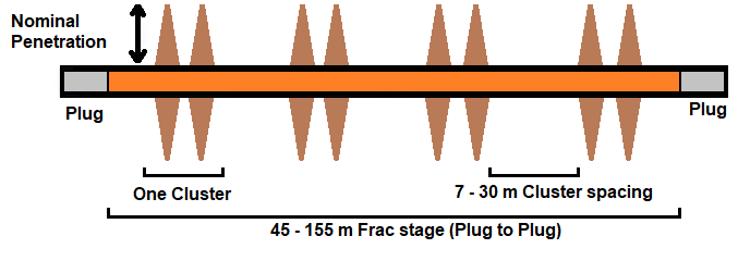
The number of perforation guns utilized in each fracture stage, as depicted in Figure 2, is specified as Clusters per stage. In general, three to eight clusters per stage are employed in the industry. The distance between clusters might range from 7 to 30 meters (25 to 100 feet). Because hydraulic fracturing energy is confined to limited-entry sites, a smaller number of clusters in each stage may be ideal for establishing longer fracture networks. A greater number of clusters per stage results in a bigger surface area near the wellbore, which can increase early hydrocarbon recovery. Because more clusters are needed to complete a specified area when the spacing is reduced, the completion size is deemed big [24].
Pumping-Time
The pumping time refers to the duration of the acidization stage, pad stage, slurry stage, and flush stage. This parameter is critical in the design of Hydraulic fracturing as it has direct control over the other design parameters. Having a short acidizing stage might not be sufficient to clean the perforations of cement or debris. This might lead to an increase in surface pressure and inefficient fluid flow into the formations which limit the efficiency of the stages to follow. During the pad stage, most of the fracture network is created. Therefore, a short pad stage might reduce the required size of the fracture causing limited contact with the reservoir and additional problems such as sanding off the wellbore during the proppant stage. Therefore, enough pumping rate and pumping time should be designed to ensure large fracture networks that are highly conductive. The slurry stage is where substantial amounts of proppants are pumped to fill the fracture and prevent it from closing during production. However, if the duration of this stage was short, then the fracture might not be entirely filled with proppants and hence part of it will close during production. On the other side, if this stage was exceedingly long, the proppants might fill the whole fracture and cause sanding off the wellbore. The flush stage is the final stage where it is needed to flush out any remaining proppants inside the wellbore. Having a short flush stage might not be adequate to empty the casing/tubing of all the proppants. This will lead to proppant production that might damage parts of the surface equipment such as the separators if not designed to handle solids production.
Challenges and discussion
ERD Challenges
As discussed previously, many factors threaten the success of an ERD well. Some of these challenges are briefly covered in this section:
Hole Cleaning
During an ERD well, whole cleaning is essential. A badly cleaned hole results in the creation of cutting beds, reduction in annulus area, and an increase in torque and drag forces. Furthermore, if an increase in Equivalent Circulating Density (ECD) occurs, the pipe may become trapped, increasing the danger of losing the hole. This parameter is critical, particularly for holes with a big diameter and a steep inclination angle. The following are some key aspects to consider when cleaning a hole [25]:
- Always ensure a high penetration rate with an average of around 100 m/hr,
- Avoid exceeding a maximum inclination angle of around 60° for most of the wells,
- Evade drilling wells that exceed 3000 m in the horizontal direction,
- Disable the rotation of the drill string when sliding.
Equivalent Circulating Density (ECD)
Since ERD wells have a significant measured depth (MD) relative to their TVD, the ECD impacts are thought to be quite significant than any other ordinary well. With the high flow rates and rotation speed needed, the hole cleaning parameters might be extremely harsh and difficult to control. Changes in ECD can have a major influence on wellbore stability, resulting in lost circulation, significantly higher standpipe pressures than normal, reduced Rate of Penetration (ROP), and a negative impact on reservoir productivity [26]. Because ECD is so important to the procedure, the fluid utilized must have certain properties. It should be very thin and, within hole cleaning constraints, before going through the casing and cementing process. It should also have strong “Shear thinning capabilities.” When attempting to achieve a compromise between flowing the fluid through the hole with the lowest possible plastic viscosity and the need for cleaning the hole and suspending the particles, critical circumstances will occur. The flow rate selected should also consider reducing cuttings development and avoiding excessive ECD
generation. The kinematic viscosity of the base fluid must be modest to improve wellbore cleaning while decreasing ECD impacts. Furthermore, approximately three or more separate drill strings will be required for every ERD project. This will maintain the required hydraulics and torque capabilities while controlling ECD variations. ECD management may also be influenced by the tool joint used.
Torque and Drag Forces
The torque and drag forces are affected by several factors, including the drill string design, trajectory route, hole size, drilling fluid, and others. If the torque and drag forces get high enough, they may form a barrier that prevents the casing and completion equipment from being installed. It can also limit the Weight on Bit (WOB) and pose complications when sliding or sidetracking. When all these issues are combined, the overall depth that can be achieved is reduced. In general, both the torque and drag forces are affected by the build-up rate, friction factor, inclination angle, kick-off points (KOP), mud density, and others [25].
Hydraulic Fracturing Challenges
Many factors can affect the efficiency of the hydraulic fracturing job and cause a reduction in fracture conductivity and well productivity. Some of these factors are briefly discussed as follows:
Proppant Embedment and Crushing
When proppants are injected into the fracture, they will be in direct contact with the formation rock e.g., shale. As the closure pressure increases, embedment or crushing might occur depending on the mechanical properties e.g., the elastic modulus of rock and proppants [27]. In general, as the elastic modulus of the formation decreases, it becomes more flexible and easily deformable, so embedment is more likely to occur. If the elastic modulus was large, the whole rock would be stiffer making it harder to deform. Therefore, high stresses would lead to proppant and/or formation crushing.
Rock Swelling
Shale reservoirs can be of different properties where some can be ductile and others brittle in nature. Therefore, careful analysis should be conducted before selecting a design plan. This selection should take into consideration how the shale, proppants and fluids would interact together. Previous studies focused on the effect of fluids on shale properties. Figure 3 shows the hardness of a shale rock sample, retrieved from the Bakken field, after being exposed to several types of fluids. As can be seen, large modifications in the shale’s hardness occurred in all the cases, but the largest effect was recorded for slickwater. Slickwater is currently the most common type of fluid used in shale gas reservoirs [28].
![Figure 3: Brinell hardness number for lower Bakken shale samples relative to fluids [28].](/fulltextimages/7963/fig_3.png)
Cluster Spacing (Evolution of Stress shadows) The increase of stresses close to hydraulically fractured locations is known as stress shadow. The stress shadow renders the fracture-propagation pressure to be higher than the original stage when a second hydraulic fracture is performed parallel to the current one. It is an essential consideration in horizontal and extended reach wells. Stronger stress shadows are to be predicted as cluster spacing is lowered. As a result, fluid distribution is disrupted throughout all hole clusters, resulting in a reduced propped surface. This will eventually have an influence on hydrocarbon recovery [29, 30]. Recently, some studies were conducted to find the impact of having a non-uniform perforation cluster spacing on the fracture geometry. It was observed that the non-uniform perforation spacing results in greater stress shadows which can hinder the fracture growth. The uniform perforation spacing showed a more homogeneous behavior for the multi-frac growth due to the sufficient perforation spacing that minimizes interference effects [31].
Well Spacing (Frac Hits)
The distance between two wellbores is referred to as well spacing. It is critical since numerous studies have shown that finding the right site for wells may improve well production. Because unconventional reservoirs have low permeability (less than 0.1 mD), obtaining an economic rate requires numerous hydraulically fractured wells in the same geological region. Because hydraulic fractures can reach deep into the reservoir, interference between wells is possible [11].
Interference among wells can occur in a variety of ways, including:
- While a nearby well is being stimulated, a new well is being drilled. In this instance, the fracturing fluid injected into the wellbore penetrates deep into the formation, causing the formation pore pressure to rise. If a new well is being drilled in a nearby area, the pore pressure change may not be taken into consideration, resulting in an underestimation of the needed mud weight during drilling. If the hydrostatic pressure of the drilling mud was smaller than the new pore pressure of the formation, this may result in underbalanced drilling conditions. To avoid drilling in these situations, a heavier mud weight will be needed to keep the situation balanced.
- While a parent’s well is producing, a child’s well is being stimulated. A fresh stimulated well is referred to as a child well, whereas an older well that is already producing hydrocarbons is referred to as a parent well. The elevated stress levels created by stimulating the child well may impact the parent’s production rate in this situation. These pressures can cause new fractures to propagate into an already damaged area. This is due to a reduction in poro-elastic stresses near the parent well because of reservoir depletion. This result was observed in the Wolfcamp formation in the Permian Basin, where the parent well’s output dropped dramatically. However, after stopping hydraulic fracturing operations for a few months, the output rate returned to normal [32, 33].
- Two fractured wells are producing simultaneously. It is expected that the stimulation of child wells has been concluded at this point, and they are now ready for production. When the well spacing between the two wells was insufficient, it was discovered that child well production rates were lower than predicted. When compared to parent wells, child wells in the Permian Basin exhibited a 30% drop-in production rates [34]. Child wells located within 300 meters of a parent well had a greater likelihood of having lower production rates than those located further away [35]. The drop in production rate for child wells may be addressed by increasing well spacing, which improves their performance. It should be noted, however, that increasing well spacing reduces the total number of wells per area, which may lower the field’s overall production [11].
- Two wells next to each other are being stimulated. Depending on the equipment and resources available, this procedure can be done in a simultaneous frac or a zipper frac. Zipper frac, on the other hand, is more prevalent during the development period. Interference can occur as a type of communication between fracturing fluids utilized in both wells, depending on the distance between them. Frac hits are the consequence of hydraulic fractures propagating into neighboring wells, causing interference. Because the proppants cannot cover all the areas where the fluid entered, as illustrated in Figure 4, this type of interference should not be expected to persist throughout the well’s production life. As the fracture closes, contact between the wells will be lost during production [36].
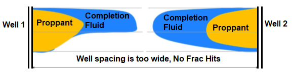
Finding the optimal well spacing is critical for optimizing hydraulic fracturing operations. By monitoring the interference impacts between wells, frac hits can be utilized to tackle this problem. Figure 4 depicts the stimulation of two wells without frac hits. This instance implies that the well spacing is too large and that some hydrocarbons may still be trapped and unstimulated between the two wells. When modest proportions of frac hits are observed, the optimal spacing is reached when the space between the wells can no longer be considered too broad or too tight [36].
Outlook
Extended-reach drilling (ERD) has been here for a while, but the pace of technological advancements is picking up in response to the industry’s ever-increasing problems in a world where the “easy oil” has already been discovered. When the borehole becomes unstable owing to time exposure, geomechanical interaction, unfavorable pressure differential, or drilling fluids interaction, the ERD limit is often achieved. When these conditions occur, the drill string experiences a rapid increase in torque and drag that is unrelated to the hole’s dogleg severity or the length of its drilled section. Another indication that the ERD has reached its limit is when the drill string can no longer travel towards the target depth due to drag forces. This impact differs from the previous in that it is unrelated to the friction factor, which remains constant. It is instead linked to the total length drilled as well as the DLS of the hole as dug. Finally, in rotary steerable applications, rotating is employed to overcome friction and move the drill string. However, when the torque capacity of the tubulars is achieved, the ERD limit is reached.
Before determining the optimum well spacing, it is critical to evaluate the size of the completion design. A completion with high cluster spacing and modest quantities of proppants is referred to as a small-sized completion design. It is likely that certain sections of the reservoir between the parents well and the child well will stay unstimulated if the parent well is modest. The sections between the two wells will most likely be overstimulated if the parent well has a big completion size, but this depends on the distances between the wells. Overstimulation would not be beneficial for tight well spacing since it would impact the production rate of both wells over time, as previously mentioned. Furthermore, the total cost of the design will be significantly higher, and the increased production costs may not be justified.
Conclusion
The application of both ERD wells and Hydraulic fracturing operations within a single well has been utilized in several unconventional reservoirs. This is to increase the contact of the wellbore with those low permeability reservoirs by controlling its trajectory and fracture directions. Several parameters can impact the success of ERD operations such as the torque and drag forces, equivalent circulating density, and hole cleaning. Therefore, these wells should be carefully planned by considering the best approach for the design of drill string, hydraulics, and casings. Instead of the conventional casing design, tie-back, floatation, and partial-flotation methods could be implemented. However, innovative technologies are still needed that can address and solve the challenges of ERD wells such as improvements to geosteering, friction reduction, and others. Achieving the optimal hydraulic fracturing design considers several variables, including fluid type, proppant properties, completion size, well spacing, and operational expenses. Selecting a suitable fracturing fluid is crucial to creating large fracture networks and transporting proppants.
Slick water fluids are preferred for brittle formations, whereas cross-linked fluids are better in ductile formations. Pumping rate and pumping time significantly impact the success of the treatment design, especially regarding the fracture size and proppant distribution. Therefore, careful consideration of this parameter is needed during the design stage. Additionally, it was shown that to enhance the final recovery of lower permeability rocks, a substantial number of clusters and close well spacing are required. Although shorter cluster-to-cluster separation can increase productivity early in the process, it is offset by greater completion costs and operational issues due to stress shadowing or cluster communication. Another crucial factor that can influence the outcomes of hydraulic fracturing is the interference effects. Well spacing dominates inter-well interference, which can lead to enhanced hydrocarbon recovery when the optimal distance is employed. Monitoring the frac hits between wells can help determine optimal well spacing. Optimal spacing is also influenced by completion design, with larger completion designs requiring wider spacing and smaller designs requiring tighter spacing.
References
-
Johnson H, Dorè AG (2010) Unconventional oil and gas resources and the geological storage of carbon dioxide: Overview. Petroleum Geology Conference series 7: 1061- 1063.
-
Arthur MA, Cole DR (2014) Unconventional hydrocarbon resources: Prospects and problems. Elements 10(4): 257-264.
-
Nair VC, Gupta P, Sangwai JS (2018) Gas Hydrates as a potential energy resource for energy sustainability. Green Energy and Technology, pp: 265-287.
-
Zhang K, Tan B, Zhang W, Sun Y, Zheng J, et al. (2021) Design of a new acoustic logging while drilling tool. Sensors 21(13): 4385.
-
Downton G, Hendricks A, Klausen TS, Pafitis D (2000) New directions in rotary steerable drilling. Oilfield Review.
-
Bou Hamdan KF, Harkouss R, Chakra HA (2015) An overview of Extended Reach Drilling: Focus on design considerations and drag analysis. International Mediterranean Gas and Oil International Conference, MedGO, Mechref, Lebanon.
-
Walker MW (2012) Pushing the extended reach envelope at Sakhalin: An operator’s experience drilling a record reach well. SPE/IADC Drilling Conference and Exhibition, San Diego, California, USA.
-
Osiptsov AA (2017) Fluid Mechanics of Hydraulic Fracturing: a Review. Journal of Petroleum Science and Engineering 156: 513-535.
-
Xu C, Kang Y, You Z, Chen M (2016) Review on formation damage mechanisms and processes in shale gas reservoir: Known and to be known. Journal of Natural Gas Science and Engineering 36: 1208-1219.
-
Gharibi A, Zoveidavianpoor M (2015) Hydraulic Fracturing for Improved Oil Recovery. Journal of Advanced Research in Fluid Mechanics and Thermal Sciences 9(1): 1-18.
-
Bou-Hamdan K (2020) Key Design Considerations for Maximizing the Recovery Rate of Unconventional Reservoirs. The Way Ahead (SPE).
-
Rudi Rubiandini RS (2008) Extended Reach Drilling (ERD) design in deepwater application. IADC/SPE Asia Pacific Drilling Technology Conference and Exhibition, Jakarta, Indonesia.
-
Aarsnes UJF, van de Wouw N (2018) Dynamics of a distributed drill string system: Characteristic parameters and stability maps. Journal of Sound and Vibration 417: 376-412.
-
Alkhaldy M, Alsaadi D, Al-Shuaibi N, Al-Omani S, Moustafa S, et al. (2016) Innovative approach in sidetracking wells in Kuwait brown field development reduces drilling hazards and improves well productivity. IADC/SPE Asia Pacific Drilling Technology Conference, Society of Petroleum Engineers, Singapore.
-
Busahmin B, Saeid NH, Alusta G, Zahran ESMM (2017) Review on hole cleaning for horizontal wells. ARPN Journal of Engineering and Applied Sciences 12(16).
-
Lee J, Cullum D, Friedheim J, Young S (2012) A new SBM for narrow margin extended reach drilling. SPE/IADC Drilling Conference, San Diego, California, USA.
-
Al-Muntasheri GA (2014) A critical review of hydraulic- fracturing fluids for moderate to ultralow- permeability formations over the last decade. SPE Production and Operations 29(4): 243-260.
-
Lemaire E, Levitz P, Daccord G, Van Damme H, Sader JE, et al. (2013) Maximizing Fracture Conductivity with Proppant Partial Monolayers : Theoretical Curiosity or Highly Productive Reality ? SPE Annual Technical Conference and Exhibition, Houston, Texas.
-
Liang F, Sayed M, Al-Muntasheri G, Chang FF (2015) Overview of existing proppant technologies and challenges. SPE Middle East Oil and Gas Show and Conference, Manama, Bahrain.
-
HY Z, Shen JD (2017) Recent Advances in Proppant Embedment and Fracture Conductivity after Hydraulic Fracturing. Petroleum & Petrochemical Engineering Journal 1(6): 1-4.
-
Ramlan AS, Zin RM, Abu Bakar NF, Othman NH (2021) Recent progress on proppant laboratory testing method: Characterisation, conductivity, transportation, and erosivity. Journal of Petroleum Science and Engineering 205: 108871.
-
Terracina JM, Turner JM, Collins DH, Spillars SE (2010) Proppant selection and its effect on the results of fracturing treatments performed in shale formations. Proceedings - SPE Annual Technical Conference and Exhibition, Florence, Italy.
-
Belyadi H, Fathi E, Belyadi F (2019) Proppant characteristics and application design. Chapter 6, Hydraulic Fracturing in Unconventional Reservoirs, pp: 71-95.
-
Jaripatke OA, Barman I, Ndungu JG, Schein GW, Flumerfelt RW, et al. (2018) Review of Permian completion designs and results. SPE Annual Technical Conference and Exhibition, Dallas, Texas, USA.
-
Agbaji AL (2018) Optimizing the planning, design and drilling of extended reach and complex wells. SPE/ DGS Saudi Arabia Section Technical Symposium and Exhibition.
-
McDermott JR, Viktorin RA, Schamp JH, Barrera MW, Fleming JM, et al. (2005) Extended Reach Drilling (ERD) technology enables economical development of remote offshore field in Russia. SPE/IADC Drilling Conference, Amsterdam, Netherlands.
-
Alramahi B, Sundberg MI (2012) Proppant embedment and conductivity of hydraulic fractures in shales. 46th US Rock Mechanics / Geomechanics Symposium, Chicago, Illinois.
-
Kurz B, Schmidt D, Cortese P (2013) Investigation of improved Conductivity and Proppant Applications in the Bakken Formation. Society of Petroleum Engineers - SPE Hydraulic Fracturing Technology Conference, The Woodlands, Texas, USA.
-
Suarez M, Pichon S (2016) Completion and well spacing optimization for horizontal wells in pad development in the Vaca Muerta shale. SPE Argentina Exploration and Production of Unconventional Resources Symposium, Society of Petroleum Engineers, Buenos Aires, Argentina.
-
Wilson A (2016) Completion and Well-Spacing Optimization for Horizontal Wells in Pad Development. Journal of Petroleum Technology 68(10): 54-56.
-
Michael A (2021) Hydraulic Fractures from Non- Uniform Perforation Cluster Spacing in Horizontal Wells: Laboratory Testing on Transparent Gelatin. Journal of Natural Gas Science and Engineering, 95: 104158.
-
King GE, Rainbolt MF, Swanson C (2017) Frac hit induced production losses: Evaluating root causes, damage location, possible prevention methods and success of Remedial treatments. SPE Annual Technical Conference and Exhibition, San Antonio, Texas, USA.
-
Rainbolt MF, Esco J (2018) Frac hit induced production losses: Evaluating root causes, damage location, possible prevention methods and success of remediation treatments, part II. SPE Hydraulic Fracturing Technology Conference and Exhibition, Society of Petroleum Engineers, The Woodlands, Texas, USA.
-
Ajisafe F, Solovyeva I, Morales A, Ejofodomi E, Porcu MM (2017) Impact of well spacing and interference on production performance in unconventional reservoirs, Permian Basin. SPE/AAPG/SEG Unconventional Resources Technology Conference, Austin, Texas, USA.
-
Ajani A, Kelkar M (2012) Interference study in shale plays. SPE Hydraulic Fracturing Technology Conference, Society of Petroleum Engineers, The Woodlands, Texas, USA.
-
Cao R, Li R, Girardi A, Chowdhury N, Chen C (2017) Well interference and optimum well spacing for Wolfcamp Development at Permian Basin. SPE/AAPG/ SEG Unconventional Resources Technology Conference, Austin, Texas, USA.
- Nigeria’s Vulnerability in the Face of Global Energy Policy
- A Simulation Study of Investigation of Optimum Oil Production Performance by Applying Various Gas Injection Methods in Oil Reservoir
- Characterization of Permo-Triassic Reservoirs through Thermal Maturity Assessment of Westphalian Source Rocks in the Cheshire Basin
- Influence of Microwax on the Rheological and Thermal Behaviour of a Wax Crude Oil
- Real-Time Monitoring and Performance Optimization of Steam Injection in Heavy Oil Reservoirs Using Fiber Optic Sensing and Integrated Predictive Simulation Models
- Rapid On-Site Determination of the Total Petroleum Hydrocarbon Content of Soils by Handheld Fourier Transform Near-Infrared Spectroscopy: Development of a Global, Site- and Scanner- Independent Calibration Model