Mathematical Modeling of Heat Transfer from Geothermal Zones to Natural Gas Hydrate Reservoirs
An analytical model was developed in this study for predicting the dynamic temperature profile in natural gas hydrate (NGH) reservoirs that receive heat energy from a geothermal layer for accelerating gas production. The analytical model was validated by a comparison of its result to the result given by a numerical model. The expression of the analytical model shows that, for a given system, the heat transfer is proportional to the mass flow rate and the temperature drop along the heat dissipator wellbore. Applying the analytical model to the NGH reservoir in the Shenhu area, Northern South China Sea, allowed for predicting the dynamic temperature profile in the NGH reservoir. The model result reveals that the NGH reservoir temperature should rise quickly at any heat-affected point, but it should propagate slowly in the radial direction. It should take more than two years to dissociate NGH within 20 m of the heat dissipator wellbore due to only thermal stimulation. Therefore, the geothermal stimulation method should be used as a technique for accelerating gas production with depressurization scheme. The formation of gas phase due to the NGH dissociation should reduce the thermal conductivity of the NGH reservoir, while the water phase dropped out from the dissociation should increase the thermal conductivity. The resultant effect should be investigated in the future in laboratories and/or numerical simulation of the dynamic water-gas two-phase flow coupled with heat-transfer mechanism.
Introduction
Natural gas hydrates (NGH) trap a tremendous amount of natural gas in on shore and offshore reservoirs worldwide. The global reserve of NGH is about 1015 ~ 1018 standard cubic meters [1]. With the ever-increasing demand for energy, NGH is considered as a potential energy sector for an increasing number of countries [2]. Compared to traditional liquid fossil fuels the natural gas stored in the NGH is favored even more with its ecologically friendly nature owing to its low-carbon content. The global initiative to restore a low- carbon planet has made NGH more attractive than other energy sources. The tremendous amount of reverse NGH and its cleanness have accounted for its increasing attractiveness to be a promising energy source for the next generations of humankind [3].
Research and field pilot studies on marine GNH have gained a strong momentum in the past two decades. Fundamental research in national programs investigates NGH petro physical properties and geological characterization of NGH reservoirs [4, 5]. Filed pilots test gas well productivity in NGH reservoirs [6, 7]. While these studies continue to deepen people’s understanding of properties of NGH reservoirs and challenges in field operations during natural gas extraction from the NGH sediments, Efforts are shifting from being stagnant with the documented huge reserve amount [8] to more relevant technical and economic studies on NGH pay zone potentials, gas well productivity, and well completion/ stimulation techniques [9, 10].
Recently Japan, China and India have carried out well testing and gas production from NGH [11, 12, 13, 14, 15]. The currently tested methods for exploration and production of natural gas from oceanic NGH include
- Depressurization,
- Thermal Stimulation,
- Thermodynamic inhibitor injection, and
- Combination of some of these methods.
Guo et al. [16] presented a feasibility study of harvesting natural gas from seabed hydrates using moving risers. This method has not been tested.
The depressurization method decreases the pressure in NGH deposit below the hydrate dissociation pressure [17, 18]. The thermal stimulation method uses surface- provided hot water/brine/steam to heat the NGH deposit above hydrate dissociation temperature [19, 20, 21]. The thermodynamic inhibitor injection method involves injection of chemicals, such as salts and alcohols, to change the hydrate pressure–temperature equilibrium conditions [22, 23]. The one example of trials using the combined method was reported by Moridis et al. [24, 25].
The depressurization-based methods are commonly used due to their simplicity, technical effectiveness, and lower cost. However, due to the strong endothermic effect of the dissociation and the Joule-Thompson cooling effect due to the rapidity depressurization, the NGH zone can experience steep local temperature drop and zone-wide temperature decline as the NGH dissociation takes place [3, 26]. The work of Kurihara et al. [27] shows that a steep local temperature drop can cause formation of secondary hydrate and ice near the producing wellbore. This would undermine well productivity due to flow restriction/choking the well. The zone-wide temperature decline due to gas expansion can reduce long-term productivity of the well as the in-situ temperature deviates from the three-phase equilibrium. Based on computer simulation, Hong et al. [28] also reported that the NGH zone can experience a significant decline in temperature because of reservoir cooling due to the endothermic dissociation. Result of their study suggests that heat transfer is the dominant mechanism controlling the NGH dissociation process. This phenomenon was investigated by Moridis et al. [24]. and verified in field testing by Qin et al. [29]. Therefore, the depressurization-based method requires a slow and graduate change of pressure and temperature to maintain long-term production. Without external heat supply to the NGH zone, it is difficult for the depressurization meth of be efficient. Moridis et al. [30] experimented with gas production from NGH zone of 55 -ft thick by circulating warm water and obtained an increased gas production peaked at 53 Mscfd. The result confirmed that the replenish of heat into active producing NGH reservoirs can facilitate a longer production life span for the NGH zone.
The currently tested thermal stimulation methods involve heat energy provided by warm water or electricity from the surface. The hydrate dissociation that solely relies on conventional thermal stimulation has been proven not adequate to be sustainable because it is slow, inefficient, and excessively energy demanding. Introducing warm water into NGH zone could also have adverse effects on the relative permeability to the gas phase. Electrical heating of the NGH zone is even a slower and less efficient process than the water-heating. The use of inhibitors for producing gas from NGH is limited owing to their high cost, short-term effectiveness, and risks of formation damage [22, 23].
In summary, none of these methods has been demonstrated to be economical due to low productivity of wells. Other factors affecting the NGH reservoir development include wellbore collapse and excessive sand production. These two issues arose because of reducing wellbore pressure in depressurization and thermal stimulation for improving well productivity. Although some novel ideas have been proposed to solve these problems, including the use of radial lateral wells [31], frac-packed wells [21, 32] and horizontal snake wells [33, 34], they have not been tested in the field.
Apparently, the thermal stimulation is the most promising method if the problems of excessive energy-demand and adverse effect of water on the gas relative permeability are solved. Fu et al. [35] proposed a new idea for thermal stimulation using geothermal energy. It involves using a y-shaped well couple to transfer the heat in a geothermal reservoir at a deeper depth to the NGH zone through a non- water contacting horizontal lateral hole. Result of their mathematical modeling shows that the temperature in the heating lateral hole can be significantly higher than the dissociation temperature of NGH. But there is a gap between their mathematical model and well production forecast because the heat transfer efficiency to the NGH zone is not known. This study fills the gap by developing an analytical model for heat transfer into the NGH zone. The analytical model was verified by a numerical model for its correctness.
System Description
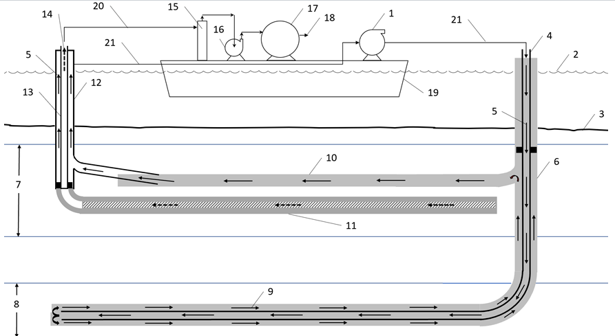
Figure 1 shows a schematic diagram of a y-shaped well couple proposed by Fu et al. [35] for producing natural gas from a subsea NGH reservoir. In the initial step of operation, seawater is injected into the inner casing 4 through a flexible hose 21 by a circulating pump 1 assembled on a production ship 19 deployed on the sea surface 2. The gas hydrate could be located up to hundreds of meters below the seafloor 3. The seawater 5 flows in the inner casing to the horizontal wellbore located in the geothermal zone 8. The water is heated up to a temperature of the geothermal zone, which is dependent on the depth of geothermal zone. The warm seawater 9 travels through the annulus area and arrives at the heat dissipator wellbore 10 located in the gas hydrate zone 7. The heat of water in the wellbore transfers into the gas hydrate zone. When the temperature in the gas hydrate zone rises to hydrate dissociation temperature, the dissociated natural gas and liquid flow into the horizontal production wellbore 11. The natural gas and liquid steam
14 flows up through the inner casing 13 of the production wellbore. The produced gas and water are collected and released through flexible hose 20 to separator 15. The liquid stream, which is mainly water, is disposed to the sea. The produced natural gas is compressed by a gas compressor 16 and stored in gas tank 17, which is later transported to pipeline network 18 or shipped for sale directly. After the heat in the warm water is dissipated into the hydrate formation, the seawater gets less warm and flows into the annulus of the production wellbore 12, and then gets circulated by pump 1. Now the injection seawater has completed a utilization cycle. The connections between the ship and the wellheads are flexible to account for the movement of the ship.
Mathematical Models
The system depicted in Figure 1 presents a technique of utilizing geothermal energy through a y-shaped wellbore couple to facilitate the production of natural gas from the NGH reservoir, which eliminates the need to burn fossil fuels or use electricity to heat the injection fluid. This process not only saves energy but also reduces carbon footprint. The gas well productivity depends on the heat transfer efficiency from the heat dissipator wellbore deep into the NGH reservoir where the horizontal production wellbore is placed. An analytical model was developed in the study to quantitively predict the temperature rise in the NGH reservoir. The analytical model verified by a numerical model for its correctness.
Analytical Model
Consider the horizontal heat dissipator wellbore 10 shown in Figure
Consider the horizontal heat dissipator wellbore 10 shown in Figure 1. The following assumptions are made for modeling the heat transfer process: • The reservoir is homogeneous and isotropic with constant density, thermal conductivity, and specific heat. • The reservoir is considered infinitely large as compared to the wellbore size.
The governing equation of temperature is the commonly known diffusivity equation expressed as $$ \left| \frac {1}{r} \frac {\partial}{\partial r} \left(r \frac {\partial T}{\partial r}\right) = \frac {1}{\beta} \frac {\partial T}{\partial t} \right| $$ (1) where T is temperature in o_C_, r is distance from the wellbore center line in meter, t is time in second, and b is thermal diffusivity constant defined by k c β ρ = (2) s ps where K is rock thermal conductivity in W/m-o_C_, rs is rock density in kg/m3, and Cps is rock heat capacity at constant pressure (specific heat) in J/kg-o_C_.
The initial condition is expressed as T = Ti at t = 0 for all r (3)
where Ti is initial reservoir temperature. The boundary condition at the wellbore is expressed as $$ = - K \left[ \frac {d T}{d r} \right] _ {r} $$ $$ q _ {r W} = - K \left[ \frac {d T}{d r} \right] _ {r = r _ {w}} $$ for all t (4) rW r r W where qrw is rate of flow of heat per unit time per unit area of wellbore in J/s-m2. For a circular wellbore with radius rw and length L, the following relation holds true:
$$ q _ {r W} = \frac {Q _ {r W}}{2 \pi r _ {W} L} \tag {5} $$
rW rW W
2 where Qrw is rate of flow of heat per unit time in J/s. Substituting Equation (5) into Equation (4) and rearranging the latter gives $$ r = - r _ {W} \left[ \frac {d T}{d r} \right] _ {r} $$ $$ \frac {Q _ {r W}}{2 \pi L k} = - r _ {W} \left[ \frac {d T}{d r} \right] _ {r = r _ {w}} $$ rW W r r for all t. (6)
2 w The solution of Equation (1) takes the following form (see Appendix A for derivation):
$$ T = T _ {i} + \frac {Q _ {r _ {W}}}{4 \pi L K} E _ {i} (s) \tag {7} $$
( ) 4 W r
where Ei(s) is exponential integral and
2 $$ s = \frac {r ^ {2}}{4 \beta t} \tag {8} $$
The heat flow rate from wellbore to reservoir can be calculated by $$ Q _ {r _ {W}} = C _ {p l} \dot {m} _ {p} \left(T _ {i n} - T _ {o u t}\right) \tag {9} $$ where Cpl is the heat capacity of the fluid inside the wellbore in ( ) / . J kg ℃, p mis the mass flow rate inside the wellbore in kg/s, and Tin and Tout are fluid temperatures in at the inlet and outlet of the wellbore, respectively.
Numerical Model
A two-dimensional numerical model was built in the finite element software COMSOL Multiphysics. Considering the symmetry of the system, the numerical model was set up with the cylindrical coordinates (r-z coordinates) with the horizontal wellbore set in z-direction and heat transfer in the radial r-direction. The governing equation for heat transfer is as follows.
$$ \rho C _ {p s} \frac {\partial T}{\partial t} + \rho C _ {p s} \boldsymbol {u}. \nabla T + \nabla . \boldsymbol {q} = Q \tag {10} $$ where r is solid density in kg/m3, Cps is the heat capacity of the solid in ( ) / . J kg ℃, T is temperature in o_C_, t is time in second, u is velocity field in m/s,
$$ q = - K \nabla T, \mathrm {a n d} Q \mathrm {i s t h e} $$
heat source in W/ m3.
The formation rock was assumed to be homogeneous and isotropic. The dimensions of the domain are 10 m of height in z-direction, 400 m of outer boundary in r-direction, and 0.3 m of inner boundary in r-direction (rw). The initial condition is given by Equation (3) and the inner boundary condition is described by Eq (4). The mesh type of the domain is linear triangular with a minimum element size of 0.02 m and a maximum size of 10 m.
Model Validation
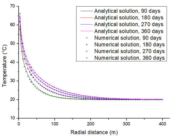
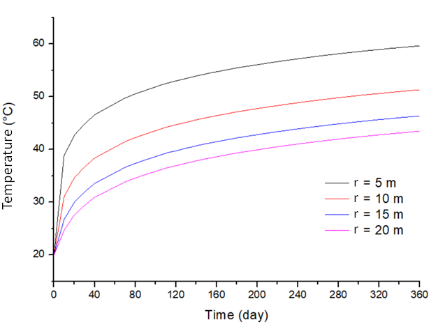
The analytical model was validated by a comparison of its result and the result given by the numerical model for an arbitrary data set shown in Table 1. A comparison of temperature profiles given by the analytical and numerical models are presented in Figure 2. This comparison indicates that the results given by the two models are identical, which implies the correctness of the analytical model. Figure 3 presents the temperature raise at different radial distances given by the numerical model. It indicates that the rate of temperature raise slows down with time.
| Model Parameter | Value | Unit |
|---|---|---|
| Solid density (r) s | 2,600 | kg/m 3 |
| Solid thermal conductivity (K) | 1 | W/m-C |
| Solid heat capacity (C ) ps | 1 | J/kg-C |
| Solid initial temperature (T) i | 20 | C |
| Liquid density (r ) L | 1000 | kg/m 3 |
| Liquid heat capacity (C ) pl | 1 | J/kg-C |
| Borehole length (L) | 10 | m |
| Borehole radius (r ) w | 0.3 | m |
| Liquid flow rate (Q) f | 0.01 | m3/s |
| Borehole inlet temperature (T ) in | 100 | C |
| Borehole outlet temperature (T ) out | 30 | C |
Table 1: An Input Data Set for Model Comparison.
Applications
The mathematical models were employed to predict the temperature increase of a NGH reservoir in the South China Sea in a scenario of using geothermal energy for producing natural gas. The example NGH reservoir is in the Shenhu area, Northern South China Sea. The pay zone is about 1,180 m below sea level and 155 m to 177 m under the mud line [36]. The average reservoir pressure and temperature are estimated to be approximately 14 MPa and 6o respectively. The NGH reservoir is composed of clayey silt in three intervals [37]. The NGH layer in interval “a” has a mean effective porosity 0.35, mean hydrate saturation about 34%, and mean permeability 2.9 md. The layer in interval “b” has a mean effective porosity 0.33, mean hydrate saturation 31%, and mean permeability 1.5 md. The layer in interval “c” has a mean effective porosity 0.32, mean gas saturation 7.8%, and mean permeability 7.4 md.
Assuiming that the major component of the natural gas in the Shenhu area is methane, the dissociation temperture of the NGH at 14 MPa is about 15o [38]. Fu et al. [35] study shows that if the heat energy in a geothermal zone (60o) at vertical depth 2,500 m is brought to the NGH layer with a water circulation rate of 10 kg/s, the temperature of water at the inlet and outlet of a 2,000 m long heat dissipator wellbore is predicted to be 47.5o and 36.5o respectively. To predict the temperature change in the NGH layer with the analytical model, Table 2 was prepared for input data.
| Wellbore length (L) | 2,000 | m |
|---|---|---|
| Thermal conductivity of rock (K) | 3.06 | W/m-C |
| Density of rock ($r_s$) | 2,600 | kg/m³ |
| Heat capacity of hydrate zone ($c_{ps}$) | 878 | J/kg-C |
| Initial rock temperature ($T_i$) | 6 | C |
| Thermal fluid density ($r_l$) | 1,030 | kg/m³ |
| Thermal fluid flow rate ($Q_f$) | 0.1 | m³/s |
| Heat capacity of thermal fluid ($C_{pi}$) | 4,184 | J/kg-C |
| Fluid temperature at inlet of wellbore ($T_{in}$) | 47.5 | C |
| Fluid temperature at outlet of wellbore ($T_{out}$) | 36.5 | C |
Table 2: Input Data to the Analytical Model for the Shenhu NGH Reservoir.
Model Result
Figure 4 presents model-calculated temperature profiles at 10 days, 20 days, and 30 days of water circulation. It indicates that the temperature should increases quickly in the vicinity of wellbore in the first month of water circulation. This is expected for the radial heat flow system.
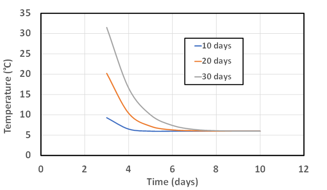
Figure 5 shows model-calculated temperature changes with time of water circulation at fixed radial distances. It implies that the temperature at a given radial distance should increases linearly with time after a while of water circulation. This is an indication of efficient heat transfer process.
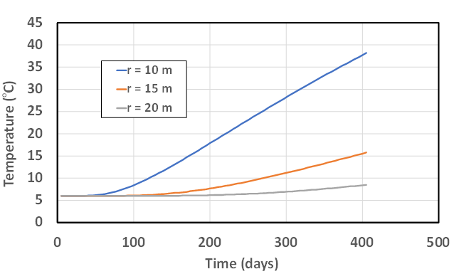
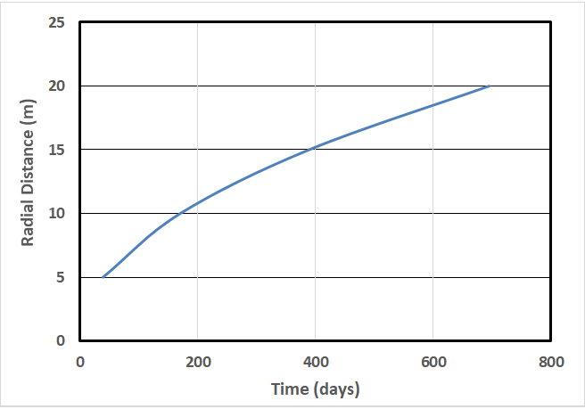
Figure 6 illustrates the model-calculated propagation of temperature front of 15oC (NGH dissociation temperature at the initial reservoir pressure) as a function of time of water circulation. It indicates a non-linear trend with a declining rate of propagation as the slope of curve drops with time. This again is expected for the radial system of heat flow.
Discussion
The data presented in Figures 4, 5, & 6 reveals that the temperature should raise quickly at any heat-affected point, but it should propagate slowly in the radial direction. It should take more than two years to dissociate NGH within 20 m of the heat dissipator wellbore due to only thermal stimulation. Therefore, the geo-thermal stimulation method should be used as a technique for accelerating gas production with depressurization scheme. In addition, because real gas law demands that the increase in temperature will raise pressure of free gas behind the 15oC front, there is a tendency of reformation of NGH if the pressure fluctuates. This suggests that the natural gas released from the NGH should be produced in time through the gas production wellbore to reduce pressure.
Result presented in this section is from using the data in Table 2. Equations (7) and (9) show that, for a given system, the heat transfer is proportional to the mass flow rate and the temperature difference (Tin - Tout). However, this temperature difference is affected by the mass flow rate through heat losses in other sections of the y-shaped well couple. An optimum mass flow rate may be found to maximize the heat transfer into the NGH layer.
The formation of gas phase due to NGH dissociation and gas production should reduce the thermal conductivity K of the reservoir, while the water phase dropped out from the dissociation may increase the thermal conductivity. The resultant effect should be investigated in laboratories and/ or numerical simulation of the dynamic water-gas two- phase flow coupled with heat-transfer mechanism. A fully coupled model for mass transfer and heat transfer should be developed in future studies.
Conclusion
Fu et al. [35] proposed a thermal stimulation method of using geothermal energy for developing gas hydrate reservoirs. It involves using a y-shaped well couple to transfer the heat in a geothermal reservoir at a deeper depth to the NGH zone through a non-water contacting horizontal lateral hole. Result of their mathematical modeling shows that the temperature in the heat dissipator hole in the NGH zone can be significantly higher than the dissociation temperature of NGH, depending on the depth of the geothermal reservoir. However, there is a gap between their mathematical model and well production forecast because the heat transfer efficiency to the NGH zone is not known. This study fills the gap by developing an analytical model for the heat transfer into the NGH zone. The analytical model was validated by a comparison of its result and the result given by a numerical model for an arbitrary data set. A comparison of temperature profiles given by the analytical and numerical models indicates that the results given by the two models are identical, which proves the correctness of the analytical model. The following conclusions are drawn.
- Applying the analytical model to the NGH reservoir in the Shenhu area, Northern South China Sea, allowed for predicting temperature profiles both in spacial and time domains. Model result reveals that the NGH reservoir temperature should rise quickly at any heat-affected point, but it should propagate slowly in the radial direction.
- It should take more than two years to dissociate NGH
within 20 m of the heat dissipator wellbore due to only thermal stimulation. Therefore, the geo-thermal stimulation method should be used as a technique for accelerating gas production with depressurization scheme.
- Because the real gas law demands that the increase in temperature will raise pressure of free gas behind the NGH dissociation temperature (15oC) front, it is expected that reformation of NGH may occur if the pressure fluctuates. This suggests that the natural gas released from the NGH should be produced in time through the gas production wellbore to reduce pressure.
- The analytical model shows that, for a given system, the heat transfer is proportional to the mass flow rate and the temperature drop along the heat dissipator wellbore. Because this temperature drop is affected by the mass flow rate through heat losses in other sections of the y-shaped well couple, an optimum mass flow rate may be found to maximize the heat transfer into the NGH layer.
Acknowledgment
The authors are grateful to BIRD for funding the project “Safe, sustainable, and resilient development of offshore reservoirs and natural gas upgrading through innovative science and technology: Gulf of Mexico-Mediterranean,” through Contract No. EC-19 Fossil Energy.
Assumptions
Consider the horizontal heat dissipater wellbore shown in Figure 1. The following assumptions are made for modeling the heat transfer process:
The reservoir is homogeneous and isotropic with constant density, thermal conductivity, and specific heat.
The reservoir is considered infinitely large as compared to the wellbore size.
Governing Equation
The governing equation of temperature is the commonly known diffusivity equation expressed as
$$\frac{1}{r} \frac{\partial}{\partial r} \left( r \frac{\partial T}{\partial r} \right) = \frac{1}{\beta} \frac{\partial T}{\partial t}$$
(A1)
where $T$ is temperature in oC, $r$ is distance from the wellbore center line in meter, $t$ is time in second, and $b$ is thermal diffusivity constant defined by
$$\beta = \frac{k}{\rho_s C_{ps}}$$
(A2)
where $K$ is thermal conductivity in W/m-$^\circ$C, $r$ is density in kg/m$^3$, $C_{ps}$ is specific heat in J/kg-$^\circ$C.
Boundary Conditions
The initial condition is expressed as
$$T = T_i \text{ at } t = 0 \text{ for all } r.$$
(A3)
where $T_i$ is initial reservoir temperature. The boundary condition at the wellbore is expressed as
$$q_{rw} = -K \left[ \frac{dT}{dr} \right]_{r=r_w} \text{ for all } t.$$
(A4)
where $q_{rw}$ is rate of flow of heat per unit time per unit area of wellbore in J/s-m$^2$. For a circular wellbore with radius $r_w$ and length $L$, the following relation holds true:
$$q_{rw} = \frac{Q_{rw}}{2\pi r_w L}$$
(A5)
where $Q_{rw}$ is rate of flow of heat per unit time in J/s. Substituting Equation (A5) into Equation (A4) and rearranging the latter gives
$$\frac{Q_{rw}}{2\pi Lk} = -r_w \left[ \frac{dT}{dr} \right]_{r=r_w} \text{ for all } t$$
(A6)
Solution
The solution of Equation (A1) is sought by Boltzmann's transformation:
$$s = \frac{r^2}{4\beta t}$$
(A7)
So that
$$\frac{\partial s}{\partial r} = \frac{r}{2\beta t}$$
(A8)
$$\frac{\partial s}{\partial t} = -\frac{r^2}{4\beta t^2}$$
(A9)
Substituting Equations (A7) through (A9) into Equation (A1) and rearranging the latter gives
$$\frac{dT}{ds} + s \frac{d}{ds} \left( \frac{dT}{ds} \right) = -s \frac{dT}{ds}$$
(A10)
Let
$$\frac{dT}{ds} = T'$$
(A11)
then Equation (A10) becomes
or
$$\frac{dT'}{T'} = -\frac{s+1}{s} ds$$ (A13)
which is integrated to obtain
$$\ln T' = -\ln s - s + c_1$$ (A14)
where $c_1$ is an integration constant. This equation is rearranged to give
$$T' = c_2 \frac{e^{-s}}{s}$$ (A15)
where $c_2$ is a constant.
Chain rule gives
$$r \frac{dT}{dr} = r \frac{dT}{ds} \frac{ds}{dr}$$ (A16)
Chain rule gives
$$r \frac{dT}{dr} = r \frac{dT}{ds} \frac{ds}{dr} = r \frac{dT}{ds} \left( \frac{r}{2\beta t} \right) = \frac{dT}{ds} \left( \frac{r^2}{2\beta t} \right) = 2s \frac{dT}{ds}$$ (A17)
Substituting Equation (A15) into Equation (A17) gives
$$r \frac{dT}{dr} = 2c_2 e^{-s}$$ (A18)
At wellbore where $s$ approaches 0, this relation becomes
$$r_w \left[ \frac{dT}{dr} \right]_{r=r_{fw}} = 2c_2$$ (A19)
Applying boundary condition Equation (A6) to Equation (A19) yields
$$\frac{Q_{fw}}{2\pi Lk} = -2c_2$$ (A20)
which gives
$$c_2 = -\frac{Q_{rw}}{4\pi Lk}$$ (A21)
Substituting Equation (A21) into Equation (A15) gives
$$\frac{dT}{ds} = -\frac{Q_{fw}}{4\pi Lk} \frac{e^{-s}}{s}$$ (A22)
which is integrated over time:
$$\int_{T_i}^{T} dT = -\frac{Q_{fw}}{4\pi Lk} \int_{\infty}^{s} \frac{e^{-s}}{s} ds$$ (A23)
or
$$T = T_i - \frac{Q_{fw}}{4\pi Lk} \int_{\infty}^{s} \frac{e^{-s}}{s} ds = T_i + \frac{Q_{fw}}{4\pi Lk} \int_{\infty}^{s} \frac{e^{-s}}{s} ds$$ (A24)
i.e.,
$$T = T_i + \frac{Q_{fw}}{4\pi Lk} E_i(s)$$ (A25)
The heat flow rate from wellbore to reservoir can be calculated by
$$Q_{fw} = C_{pi} \dot{m}_p \left( T_{in} - T_{out} \right)$$ (A26)
where $C_{pi}$ is the heat capacity of the fluid inside the wellbore in $J/(kg \cdot ℃)$, $\dot{m}p$ is the mass flow rate inside the wellbore in kg/s, and $T{in}$ and $T_{out}$ are fluid temperatures in at the inlet and outlet of the wellbore, respectively.
References
-
Klauda JB, Sandler SI (2005) Global distribution of methane hydrates in ocean sediment. Energy Fuels 19(2): 459-470.
-
Demirbas A (2010) Methane hydrates as potential energy resource: Part 2-Methane production processes from gas hydrates. Energy Conversion and Management 51(7): 1562-1571.
-
Moridis GJ, Collett TS, Boswell R, Kurihara M, Reagan MT et al. (2008) Toward production from gas hydrates: assessment of resources, technology, and potential. SPE Res Eval & Eng 12 (05): 745-771.
-
Uchida T, Tsuji T (2004) Petrophysical Properties of Natural Gas Hydrates‐Bearing Sands and Their Sedimentology in the Nankai Trough. Resource Geology 54(1): 79-87.
-
Peng C, Zou C, Lu Z (2018) Characteristics of gas hydrate reservoirs and their effect on petrophysical properties in the Muli area, Qinghai-Tibetan plateau permafrost. Journal of Natural Gas Science and Engineering 57: 266- 283.
-
Konno Y, Fujii T, Sato A (2021) Influence of Flow Properties on Gas Productivity in Gas-Hydrate Reservoirs: What Can We Learn from Offshore Production Tests?. Energy & Fuels 35(10): 8733-8741.
-
Guo B, Fu C, Liu N (2021) A Priori Assessment of Long- Term Productivity of Frac-Packed Wells for Producing Natural Gas from Marine Gas Hydrate Reservoirs. Energy Sci Eng 9(6): 884-896.
-
Paull C, Ussler W, Lorenson T, Winters W, Dougherty J (2005) Geochemical constraints on the distribution of gas hydrates in the Gulf of Mexico. Geo-Marine Letters 25(5): 273-280.
-
Ruppel C, Dickens G, Castellini D, Gilhooly W, Lizzarralde D (2005) Heat and salt inhibition of gas hydrate formation in the northern Gulf of Mexico. Geophysical Research Letters 32(4): L04605.
-
Boswell R (2007) Resource potential of methane hydrate coming into focus. JPSE 56: 9-13.
-
Li G, Moridis GJ, Zhang K, Li XS (2011) The use of huff and puff method in a single horizontal well in gas production from marine gas hydrate deposits in the Shenhu Area of South China Sea. J Petrol Sci Eng 77: 49-68.
-
Ruppel C (2014) Gas Hydrates and the Future of Natural Gas _(PDF)._ Gas Hydrates Project, Woods Hole, MA: U.S. Geological Survey.
-
Shyi-Min L (2015) A global survey of gas hydrate development and reserves: Specifically in the marine field. Renewable and Sustainable Energy Reviews 41: 884-900.
-
Max MD, Johnson AH (2016) Exploration and Production of Oceanic Natural Gas Hydrate. Springer International Publishing, pp: 39-73.
-
Zhang W, Bai F, Shao M (2017) Progress of offshore natural gas hydrate production tests in Japan and implications. Marine Geology & Quaternary Geology 37(5): 27-33.
-
Guo B, Shan L (2018) Heat Transfer in Counter- Current Two-Phase Flow Applied to Feasibility Study of Harvesting Natural Gas from Seabed Hydrates. International Journal of Heat and Mass Transfer 126: 603-612.
-
Ahmadi G, Ji CA, Smith DH (2007) Production of natural gas from methane hydrate by a constant downhole pressure well. Energy Convers Manage 48(7): 2053- 2068.
-
Li XS, Yu CG, Zhang Y, Ruan XK, Li G et al. (2016) Investigation into gas production from natural gas hydrate: A review. Applied Energy 172(15): 286-322.
-
Li G, Tang LG, Huang C, Feng ZP, Fan SS (2006) Thermodynamic evaluation of hot brine stimulation for natural gas hydrate dissociation. J Chem Ind Eng China 57(9): 2033-2038.
-
Kawamura T, Ohtake M, Sakamoto Y, Yamamoto Y, Haneda H et al. (2007) Experimental study on steam injection method using methane hydrate core samples. Proceedings of the Seventh ISOPE Ocean Mining Symposium. Lisbon, Portugal, pp: 83-86.
-
Li G, Li XS, Tang LG, Li QP (2008) Control mechanisms for methane hydrate production by thermal stimulation. Paper 5783, Proceedings of the 6th International Conference on Gas Hydrates. Vancouver, British Columbia, Canada, pp: 6-10.
-
Kawamura T, Yamamoto Y, Ohtake M, Sakamoto Y, Komai T et al. (2005) Experimental study on dissociation of hydrate core sample accelerated by thermodynamic inhibitors for gas recovery from natural gas hydrate. Proceedings of the 5th International Conference on Gas Hydrates. Trondheim, Norway, pp: 3023.
-
Najibi H, Chapoy A, Haghighi H, Tohidi B (2009) Experimental determination and prediction of methane hydrate stability in alcohols and electrolyte solutions. Fluid Phase Equilib 275(2): 127-131.
-
Moridis GJ, Reagan MT (2007a) Strategies for Gas Production from Oceanic Class 3 Hydrate Accumulations. Lawrence Berkeley National Laboratory, pp: 1-30.
-
Moridis GJ, Reagan MT (2007b) Gas Production from Oceanic Class 2 Hydrate Accumulations. Offshore Technology Conference, Houston, Texas, USA.
-
Gaydukova OS, Misyura SY, Strizhak PA (2021) Investigating regularities of gas hydrate ignition on a heated surface: Experiments and modelling. Combustion and Flame 228: 78-88.
-
Kurihara M, Funatsu K, Ouchi H, Masuda Y, Narita H (2005) Investigation On Applicability of Methane Hydrate Production Methods to Reservoirs with Diverse Characteristics. Paper 3003 presented at the 5th International Conference on Gas Hydrates, Trondheim, Norway 3: 714-725.
-
Hong H, Pooladi-Darvish M (2005) Simulation of Depressurization for Gas Production from Gas Hydrate Reservoirs. J Can Pet Tech 44(11): 39-46.
-
Qin X, Liang Q, Ye J, Lin Y, Haijun Q et al. (2020) The response of temperature and pressure of hydrate reservoirs in the first gas hydrate production test in South China Sea. Applied Energy 278: 115649.
-
Moridis GJ, Collett TS, Dallimore SR, Inoue T, Mroz T (2005) Analysis and Interpretation of the Thermal Test of Gas Hydrate Dissociation in the JAPEX/JNOC/GSC et al. Mallik 5L-38 Gas Hydrate Production Research Well. Scientific Results, pp: 162.
-
Guo B, Shaibu R, Yang, X (2020) Analytical Model for Predicting Productivity of Radial-Lateral Wells. Energies 13(23): 6386.
-
Ekhator EF, Guo B (2021) Assessing the Effect of Well completion Types on Productivity in a Class 1G Gas Hydrate Reservoir under Pseudo Steady State. Petroleum 7(4): 414-426.
-
Wan L, Shaibu R, Hou X, Guo B (2019) A Feasibility Study of Producing Natural Gas from Subsea Hydrates with Horizontal Snake Wells. OTC 29816-MS presented at the 2019 Offshore Technology Conference held in Rio de Janeiro, Brazil, pp: 28-31.
-
Mahmood MN, Guo B (2021) Productivity Comparison of Radial Lateral Wells and Horizontal Snake Wells Applied to Marine Gas Hydrate Reservoir Development. Petroleum 7(4): 407-413.
-
Fu C, Guo B, Lee J (2021) Mathematical modeling of heat transfer in y-shaped well couples for developing gas hydrate reservoirs using geothermal energy. Journal of Natural Gas Science and Engineering 96: 104325.
-
Su M, Yang R, Wu NY (2014) Structural characteristics in the Shenhu Area, northern continental slope of South China Sea and their influence on gas hydrate. Acta Geol Sin 88: 318-326.
-
Li JF, Ye JL, Qin XW, Qiu HJ, Wu NY et al. (2018) The first offshore natural gas hydrate production test in South China Sea. China Geol 1(1): 5-16.
-
Guo B, Ghalambor A (2012) Atural Gas Engineering Handbook. 2nd (Edn.), Gulf Publishing Company, Houston, pp: 277-279. Appendix A: Mathematical Modeling of Heat Transfer into Gas Hydrate Reservoirs
- Nigeria’s Vulnerability in the Face of Global Energy Policy
- A Simulation Study of Investigation of Optimum Oil Production Performance by Applying Various Gas Injection Methods in Oil Reservoir
- Characterization of Permo-Triassic Reservoirs through Thermal Maturity Assessment of Westphalian Source Rocks in the Cheshire Basin
- Influence of Microwax on the Rheological and Thermal Behaviour of a Wax Crude Oil
- Real-Time Monitoring and Performance Optimization of Steam Injection in Heavy Oil Reservoirs Using Fiber Optic Sensing and Integrated Predictive Simulation Models
- Rapid On-Site Determination of the Total Petroleum Hydrocarbon Content of Soils by Handheld Fourier Transform Near-Infrared Spectroscopy: Development of a Global, Site- and Scanner- Independent Calibration Model