Completion Design to Prevent the Production of Sand in a Well by Using Suitable Equipment
The aim of this paper is to propose a completion design to prevent the production of sand in a well named "X" (for confidential reasons) by using suitable equipment. To reach this goal, the equipment materials (metals and elastomers) must be selected. The downhole gravel pack equipment must be chosen, the well schematic drawn and the installation procedure written. The data used are the well-completion design. The well schematics are drawn by using Power Draw 2019. The results show that the recommended metallurgy is stainless steel with 13 chrome. For this case, the best equipment is the wire-wrapped screen with its slot size ranging from 0.008 to 0.012 inch, and the wash pipe size is 1.66 inch. The gravel pack packer, closing sleeve, gravel pack extension, flapper valve, safety shear joint, blank pipe, screen, snap latch and hydrogenated nitrile butadiene rubber material are selected to meet the scope of work. The total cost of the lower completion operation is 354,200$.
Introduction
In oil and gas, the purpose of drilling a well is to confirm the presence of hydrocarbons [1, 2, 3]. When the confirmation is done with studies showing proven reserves are economically viable, special equipment is installed into the well to start production: This operation is called the completion [4, 5, 6]. Well completion is defined as an operation involving the installation of production equipment in the well to bring it into production without this interface, it is impossible to safely and efficiently produce a well [7, 8, 9]. There are several types of completion depending on production objectives; these objectives must be known before designing any completion string. In some cases, to avoid sand production to occur during hydrocarbons production, screens and/or gravel pack are required to create a barrier by preventing any sand particles to enter the wellbore [10, 11, 12]. This method among sand control techniques significantly increases the production of hydrocarbon. There are several methods of sand control that vary depending on the production objectives and reservoir characteristics (porosity, permeability, fluid mobility) [13, 14, 15]. This topic is well addressed on open and cased hole gravel pack in literature [14, 16, 17]. Mostly, cased hole gravel packs with proppant packed behind the screen are installed into the well to retain formation sand from entering the production equipment [18, 19]. However, design complexity becomes more of a challenge while choosing appropriate metallurgy and equipment to resist downhole conditions in order to meet production objectives. A cased hole gravel pack is a relatively high cost, this cost includes the cost of equipment, proppant (gravel), completion fluid, pumping charge, and drilling [20, 21]. There have been several studies to determine which best completion method is economical and a result has never been obtained as each method depends on its application [22, 24]. This paper aims to control sand production in the new drilled well X. Therefore, the challenge is running the operation in an efficient, economical, and reliable manner.
To achieve the goal of this paper, objectives are set: Select the corresponding equipment; choose suitable materials (metals) and equipment (based on technical and economic analysis); propose a cost-effective design solution to solve the problem; write the installation procedure. This paper is structured in three sections: The first section deals with the introduction, and the second section talks about the data, tools, and the obtained results. The paper ends witha general conclusion.
Data, Methods and Results
To preserve the company’s confidentiality, the well is named “X” and its location is not given. It is made of 2 casings (7 5/8” from surface to 590 m, 5 ½” from 590m to 1895 m both grades are L80 and buttress thread connection). The reservoir pressure is 1580 psi and the temperature is 159°F. H2S content is low (2.5 ppm) and CO2 content is high (5 moles %), the proppant size is 20/40. Table 1 presents the data for a well-completion design.
| Temperature= 159oF | |
|---|---|
| Pressure= 1580 psi | |
| H2S cntent=2.5 PPM | |
| Reservoir Data | CO content=5% 2 |
| Reservoir interval=1875-1886 m | |
| MD= 1895 m | |
| Casing 7 5/8” from surface to 590 mID=6.875 inch | |
| Casing 5 5/8” from +/- 590 m to 1895 m ID=4.95 inch | |
| Grade=L80, connection=BTC | |
| Inclination =85° | |
| Test pressure casing =4000 psi | |
| Brust pressure: casing 7 5/8”=6889 psi; casing 5 1/2”=4988 psi | |
| Collapse pressure: casing 7 5/8”=4786 psi; casing 5 1/2”=7003.5 psi | |
| Well Data | Depth: gravel pack packer=1829 m sump packer=1889.2 m |
| Name= brine | |
| Completion fluid | Density= 1.02 SG 8.5PPG |
| Mesh size | Sieve opening inch |
| 20 | 0.0331 |
| 40 | 0.0165 |
| Slot size 1/2 | 0.00825 |
| Slot size 2/3 | 0.011 |
| Slot size is 0.008 to 0.012 inch |
Table 1: Data for well-completion design.
The Power Drawn software and economic evaluation are used to attain the aims of this paper. This is made possible through metallurgy selection, seal selection, steel selection, screen selection, and describing the installation procedure.
Metallurgy Selection, Seal Selection, Steel Selection, and Screen Selection
The partial pressure of CO2 is 79 psi and the partial pressure of H2S is 0.003 psi. The proposed metallurgy is an alloy of steel with 13% of chromium.The select metallurgy is stainless steel 316L with 13% chromium because it is resistant to corrosion. The reservoir temperature is 159°F. The H2S content is 2.5 ppm, which is less than 10 ppm. Both nitrile and hydrogenated nitrile could be used as sealing elements in this well. The proposed elastomer for the sealing elements is hydrogenated nitrile. To cover the expected plan which is to maintain productivity as long as possible, a specific screen mesh size is chosen based on the proppant size. The proppant is 20/40. The smallest mesh size is the sieve opening of 40 mesh size as shown in Table 2.
Screen gauge size range is 8 to 12 gauge. The selected screen type is wire wrapped screen. The screen size selection is function of the casing size as shown in Table 3.
| Casing OD Standards screens Nominal size Screen jacket OD Screen base pipe ID | 5” 23/8” 2.875”- 3.00” 1.995” | 5 1/2” 23/8” 2.875”- 3.00” 1.995” | 7” 7 5/8” 9 5/8” 3 1/2” 4.00- 4” 4.5”-4.75 5 1/2” 5.5” 4.25 2.992 3.548 -5.75” 4.494 |
|---|
Table 2: Screen size.
The third column in blue of Table 3 indicates the screen size used in this paper. The wash pipe OD is 80% of the screen ID. The screen size is 2 3/8 inch and the ID is 1.995 inch. Therefore,the wash pipe OD is 1.66 inch with a nominal size of 1-1/4 inch.
Well Schematic and Running Procedure
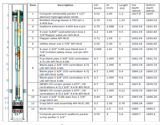
The proposed well schematic and equipment dimensions of the lower completion descriptionare depicted in Figure 1.
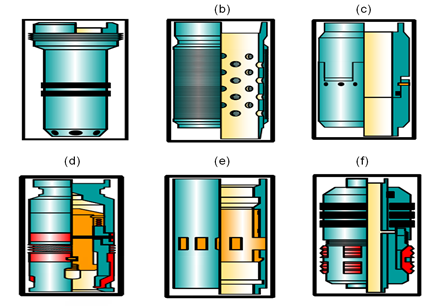
In the literature, the most used completion techniques for sand control are standalone screen and gravel pack [24, 25, 26, 27, 28, 29, 30]. Standalone screen requires running down only the screen, which filter the formation sand, it is less expensive but the screens plug quickly, and requires high maintenance costs [25, 26, 27, 28]. The gravel pack techniques consist of lowering the screens in front of the perforations and pumping the gravel into the annular space between the casing and the screen, thus filtering the fluid and preventing the production of formation sand [28, 29, 30]. Therefore, the used method in this paper is gravel pack which consists of a snap latch, screens, blank pipe, and gravel pack packer assembly as shown in Figure 2.
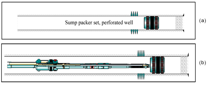
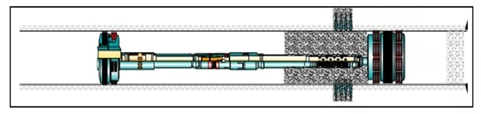
The running process of the lower completion is done in six steps. Initially, the well is found drilled, scraped, cleaned, sump packer set, and reservoir perforated. The running procedure l begins after perforating the reservoir. Pick up screens, blank pipe and run are shown in Figure 3.
In Figure 3, the next step is to set a packer, to do this, a ball is dropped into the hydro trip sub, a pressure is pumped to chase the ball to its seat, With the ball on the seat, pressure up the tubing to set the packer. Perform a mechanical push and pull test to confirm slips are gripped on the casing.
Pressure up the annulus confirmsthe packer element seal into the casing. Increase pressure to release the service tool from the packer, pickup the tool to the reverse position, and blow the ball seat as shown in Figure 4.
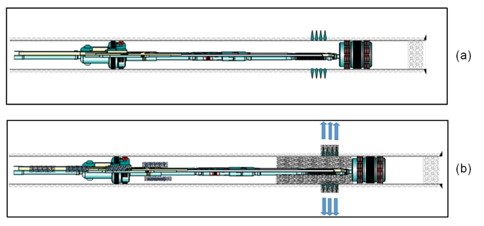
Lower back down the tool and perform gravel pack as per the program. The objective of a circulation pack is to fill the annulus and the perforations from the bottom up as shown in Figure 5.
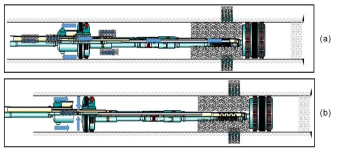
In Figure 5, the wash pipe must be spaced out so that return circulation occurs as close as possible to the bottom of the screen. As the gravel pack begins, slurry fills the annular space outside the screen and the slurry starts to dehydrate at the bottom of the screen opposite the end of the wash pipe. As packed gravel accumulates around the bottom of the screen, a higher-pressure drop is required for the fluid to enter the screen and to flow in the screen/wash pipe annulus to the end of the wash pipe, thereby inducing fluid leak-off through the perforations.The hole in the service tool in order to lower the upper completion is pulled out and put the well into production as shown in Figure 6.
Economical Evaluation
The total cost of the installation of the lower completion is presented in Table 4.
| Equipments | Unit cost ($) | Unit | Total ($) |
|---|---|---|---|
| Gravel pack packer | Not applicable | 1 | Not applicable |
| Closing sleeve | Not applicable | 1 | Not applicable |
| Extension | Not applicable | 1 | Not applicable |
| Flapper valve | Not applicable | 1 | Not applicable |
| Safety joint | Not applicable | 1 | Not applicable |
| Cross over | Not applicable | 1 | Not applicable |
| Blank pipe | Not applicable | 3 | Not applicable |
| Pup blank pipe | Not applicable | 1 | Not applicable |
| Wire-Wrapped screen | Not applicable | 2 | Not applicable |
| Snap latch | Not applicable | 1 | Not applicable |
| Sump packer | Not applicable | 1 | Not applicable |
| Rental Equipments | |||
| Equipments | Cost/day ($) | Numbers days | Total ($) |
| Service tools | Not applicable | 7 | Not applicable |
| Personal charges | |||
| Personal | Cost/day ($) | Numbers days | Total ($) |
| Specialist | Not applicable | 7 | Not applicable |
| Assistant | Not applicable | 7 | Not applicable |
| Total cost of lower completion | 354,200.00 |
Table 3: Cost of 5 ½’’ cased hole gravel pack project.
To obtain the results in Table 4, it is considered that the installation is done in seven days:Three days of preparation and four days of operation. The equipment is sold to the customers except for the service tool, which is rented to the customer. We have a specialist and an assistant who coordinate and operate the installation. For confidentiality reasons, prices will not be given. The total cost of the lower completion operation is 354,200$.
Conclusion
The goal of this paper was to choose the efficient and cost-effective lower completion equipment to prevent the production of sand in well X. To make cased hole gravel pack a successful operation, all aspects must be planned ahead. This implies selecting the most appropriate materials and equipment. We found out that the best materials were an alloy of steel with 13% of chromium for metallurgy and hydrogenated nitrile for sealing elements. Chromium adds resistance to steel in a corrosive environment, and at 159°F, 13% of chromium gives better results than 9% and most economic than 20%. Both nitrile and hydrogenated nitrile could be used in the presence of the produced fluid, completion fluid, and injection fluid, but the nitrile gives the equipment a very low life span.Hydrogenated nitrile was finally validated. The best downhole equipment was wire wrapped screen with a slot size range from 0.008 to 0.012 inch and a wash pipe size is 1.66 inch. The gravel pack packer, blank pipe, screens, closing sleeve, flapper valve, safety joint and snap latchare usedand the completion method with equipment helped to prevent sand production in well X. The total cost of the lower completion operation was 354,200 $. Also, to select the most appropriate equipment, further work must be done with the help of the production engineers designing the pumping rate volume of gravel and carrier fluid and corrosion engineers for material selection, and reservoir engineers for reservoir data.
References
-
Economides M (1994) Petroleum production systems. Prentice-Hall, US.
-
John R, Richard L (2017) Introduction to petroleum engineering. Wiley, New Jersey.
-
Alain M (2014) Geology and Geodynamics of Hydrocarbons. Encyclopedia of Energy 5: 11-15.
-
Davorin M,Cikes M, Moslavac B (2012) Sand control in well construction and operation. Springer, pp: 1-204.
-
Montrose R (2009) Completion design manual. Planete energies 16: 5-10.
-
Schlumberger (2014) Defining completion. SPE 3: 50.
-
Perrin D (1999) Well-Completion-and-Servicing Paris. EditionTechnip, Paris, pp: 1-336.
-
Economides M (1997) Petroleum well construction. Offshore technology conference, Texas 6: 30-35.
-
Bellarby J(2009) Well completion design. 1st(Edn.), Elsevier, pp: 304-367.
-
Renpu W (2011) Advanced well completion engineering. 3rd(Edn.), Elsevier, Oxford.
-
Roma B, Kuncoro BU (1995) Sand control for unconsolidated reservoirs, IATMI, Indonesia.
-
Crumpton H (2018) Well control for completions and interventions. Gulf Professional Publishing, Elsevier, Scotland.
-
Ding J, Cheng Y, Yan C, Song B, Sun H, et al. (2019) Experimental study of sand control in a natural gas hydrate reservoir in the South China sea. International Journal of Hydrogen Energy 44(42): 23639-23648.
-
Matanovic D, Cikes H, Moslavac B (2012) Sand control in well construction and operation. 1st (Edn.), Springer Environmental Science and Engineering, Springer Berlin, Heidelberg, pp: 7-200.
-
Shahsavari MH, Khamehchi E (2018) Optimum selection of sand control method using a combination of MCDM and DOE techniques. Journal of Petroleum Science and Engineering 171: 229-241.
-
Ali S (1985) Combined stimulation and sand control. Oilfield Rev 4: 20-23.
-
Penberthy W (1992) Sand control. SPE 8: 15-20.
-
Unneland T (1999) An improved model for predicting high-rate cased-hole gravel-pack well performance. SPE European formation damage conference, Netherlands.
-
Saebi S, Tyutikov S, Machado A, Curteis C, Rivero ME, et al. (2010) Design execution and results of the longest multizone cased hole gravel pack completions in Malaysia. International Oil and Gas Conference and Exhibition, China.
-
Jabbari HB (2013) Hydraulic fracturing design optimization. American Rock Mechanics Association, San Francisco.
-
Fowler J (2006) Through-tubing sand control techniques reduce completion costs, SPE.
-
Mathur PKN, Kumar N (2016) Contrast between plug- and-perf method and ball and sleeve, pp: 1-12.
-
Cheney D (1997) Petroleum Well construction, Oklahoma.
-
Chanpura RA, Hodge RM, Andrews JS, Toffanin EP, Moen T (2010) State of the art screen selection for standalone screen applications. SPE international symposium and exhibitionon formation damage Control, Lafayette, Louisiane, USA.
-
Chanpura RA, Hodge RM, Andrews JS, Toffanin EP, Moen T, et al. (2011) A review of screen selection for standalone Applications and a New Methodology. SPE Drill & Compl 26(1): 84-95.
-
Mondal S, Wu CH, Sharma MM, Chanpura RA, Parlar M (2016) Characterizing, designing, and metal mesh screens for standalone-Screen applications. SPE Drill & Compl 31(2): 85-94.
-
Hodge RM, Burton RC, Constein V, Skidmore V (2002) An evaluation method for screen-only and gravel- pack completions. SPE international symposium and exhibitionon formation damage Control. Louisiane.
-
Parlar M, Albino E (2000) Challenges accomplishments, and recent developments in gravel packing. Journal of Petroleum Technology 52(1): 50-58.
-
Martins L, Magalhaes JVM, Calderon A, Chagas CM (2005) A mechanistic model for horinzotal gravel pack displacement. SPE 10(3): 229-237.
-
Shirazi S, Frigaard IA (2020) Gravel packing: How does it work? Physics of Fluids 32: 053308.
- Nigeria’s Vulnerability in the Face of Global Energy Policy
- A Simulation Study of Investigation of Optimum Oil Production Performance by Applying Various Gas Injection Methods in Oil Reservoir
- Characterization of Permo-Triassic Reservoirs through Thermal Maturity Assessment of Westphalian Source Rocks in the Cheshire Basin
- Influence of Microwax on the Rheological and Thermal Behaviour of a Wax Crude Oil
- Real-Time Monitoring and Performance Optimization of Steam Injection in Heavy Oil Reservoirs Using Fiber Optic Sensing and Integrated Predictive Simulation Models
- Rapid On-Site Determination of the Total Petroleum Hydrocarbon Content of Soils by Handheld Fourier Transform Near-Infrared Spectroscopy: Development of a Global, Site- and Scanner- Independent Calibration Model