Obtaining More Gasoline in CCR Unit by Using of ANFIS
Naphtha Continuous Catalytic Reforming (CCR) is one of the most beneficial processes in any refineries whose duty is increasing the octane number especially heavy naphtha. In this study, the parameters were obtained from a live Distributed Control Syste (DCS) and lab during two years of operation. Firstly, important and effective parameters on changing RON were selected consulting experienced operators. Then Adaptive Neuro-Fuzzy Inference system (ANFIS) used in order to find the optimum operating conditions. The best model extracted, and obtained data were applied to the live CCR unit with the capacity of 30000 bbl day-1. There search octane number )RON( reached to 99.7 and gasoline saved (640 bbl day-1)from this increasing of RON in final gasoline pool, subsequently. The feed final boiling point 165°C, coke on catalyst 2.42 wt%, recycle gas flow rate 24.2Tonne/hr, reactor inlet temperature 527°C, catalyst transfer rate 987.24 Kg/hr and H2/HC mol ratio 2.82.
Introduction
The main goal of the catalytic reforming process is to increase the octane number especially heavy naphtha. The main reason for installing catalytic reforming units is to enhance the antiknock quality of naphtha as a blending stock for motor fuels [1]. In catalytic reforming, a large number of reactions occur, including dehydrogenation of paraffins to olefins, dehydrogenation and dehydroisomerization of naphthenes to aromatics, isomerization or hydroisomerization to isoparaffins, dehydrocyclization of paraffins and olefins to aromatics, isomerization of alkylcyclopentanes and substituted aromatics, and hydrocracking of paraffins and naphthenes to lower hydrocarbons. One of the catalytic reforming units is continuously catalyst regenerative (CCR) in which, the process contains of three or four adiabatic reactors in series with intermediate heaters [2]. Low octane hydrocarbons, similar to naphthenes and paraffin’s are needed to convert to high octane aromatics, hydrogen and other light gases via this process [3]. In recent decades, soft computing methods such as artificial neural network (ANN) and adaptive neuro-fuzzy inference system (ANFIS) [4], functional networks (FN) and support vector regression (SVR) have been successfully applied by engineers in order to find excellent solutions for various problems in petroleum industry [5, 6]. The adaptability and accuracy of these techniques have made them the common approach among scientists and researchers [7, 8]. ANN and ANFIS used in many fields; in the Heating, Ventilating and Air-conditioning (HVAC) area, additionally they have been applied in system controlling, energy management, load prediction fault diagnosis, and system identification and other applications [9, 10]. ANN is an engineering method of biological neuron which has several inputs and one output. Similar to biological neuron, ANN also has neurons which are artificial and they receive inputs from the other elements or other artificial neurons. The result is then converted by a transfer function into the output. The transfer function can be anything such as hyperbolic tangent functions, sigmoid or a step [11]. ANFIS is collected combining neural networks and fuzzy logic [12]. It has the advantages of fuzzy processing, nonlinear approximation and self-learning [13]. In the year (2015), a method for selecting the optimal reformer temperature for a reformed methanol fuel cell system was presented upon a case study of a H3 350 module produced via Serenergy A/S. The method was according to ANFIS models of the dependence of the reformer output gas composition on the reformer temperature and fuel flow [14]. In the year (2016), ANFIS was employed to propose an approach for identifying the most important parameters for prediction of daily dew point temperature (Tdew). The ANFIS model for variable selection was implemented, which includes a number of ways to recognize the parameters favorable predictions [4]. In another study, a new compensation system was done for reducing thermal errors of machine tools u. Different groups of key temperature points were recognized using a novel schema based on a Grey model GM (0, N) and fuzzy c-means (FCM) clustering method. An Adaptive Neuro-Fuzzy Inference System with fuzzy c-means clustering (FCM-ANFIS) was employed to design the thermal prediction model [15].
The aim of present study is to use the ANFIS model for identification of CCR unit in order to increase the research octane number of hydrocarbon. This evaluation discusses the capability of mathematical models to describe the behavior of present platform by existing data. In this work, reaching to max research octane number (RON) is the main target. Some important elements like reactor inlet temperature (RIT), recycle gas flow rate (RGF), Coke percentage on catalyst (CPC), catalyst circulation (CC), H2/HC and feed boiling point (FBP), have been chosen for the first step, these elements effect on the RON significantly. Data gathering for two years has been done from both laboratory tests and distributed control system (DCS), then simulation and ANFIS modeling calculation has been finished. Best condition to reach to the highest RON was achieved by selected modeling and tried in the live unit. Laboratory test of RON showed highest RON reached when results used.
Process Description of CCR Unit
In a CCR unit, the reforming reactions occur in moving bed catalytic reactors from which the catalyst is withdrawn, then regenerated and recycled. The capacity of plant was 30000 bbl day-1. The sketch of the process is shown in Figures 1 & 2.
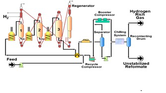
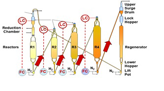
The catalyst regeneration and circulation were carried out on a continuous basis with full automatic control during all operations. A high temperature (almost 525ºC) was required to stimulate the chemical reactions which improve research octane number; hence the preheating of the feed was needed. The common feed stocks to catalytic reformers are heavy straight-run (HSR) naphtha, gasoline [180–375°F (82–180°C)] and heavy naphtha, which composed of the four major hydrocarbon groups: Paraffin, Olefin, Naphthenes, and Aromatics (PONA). The typical feed stocks and reformer products (vol %) is shown in Table 1. Moreover, feed specification of the CCR plant is presented in Table 2.
| Component | Feed (Vol %) | Product (Vol %) |
|---|---|---|
| Paraffins | 30-70 | 30-50 |
| Olefins | 0-2 | 0-2 |
| Naphthenes | 20-60 | 0-3 |
| Aromatic | 20-Jul | 45-60 |
Table 1: Range of PONA in the feed and product as two years average lab result.
| Distillation D=86 | Case 1 Jan. 2014 | Case 2 Apr.2014 | Case 3 Aug.2014 | Case 4 Dec.2014 | Case 5 Jan.2015 | Case 6 Apr.2015 | Case 7 Aug.2015 | Case 8 Dec.2015 |
|---|---|---|---|---|---|---|---|---|
| IBP ˚C | 94 | 94 | 92 | 93 | 95 | 92 | 94 | 91 |
| 10%Vol ˚C | 106 | 105 | 104 | 103 | 108 | 105 | 107 | 103 |
| 30%Vol ˚C | 112 | 113 | 108 | 110 | 113 | 112 | 113 | 109 |
| 50%Vol ˚C | 119 | 118 | 115 | 118 | 119 | 119 | 120 | 115 |
| 70%Vol ˚C | 126 | 125 | 127 | 125 | 127 | 125 | 128 | 120 |
| 90%Vol ˚C | 140 | 139 | 137 | 139 | 140 | 138 | 142 | 135 |
| FBP ˚C | 165 | 166 | 164 | 163 | 162 | 164 | 167 | 158 |
| PONA Analysis | ||||||||
| Naphtenes VOL% | 34.1 | 32.8 | 33.6 | 33.9 | 34.5 | 33.5 | 34.1 | 31.8 |
| Aromatic Vol% | 12.5 | 12.1 | 11.9 | 12 | 12.7 | 12.3 | 12.3 | 11.6 |
| Density Kgm3 | 747.7 | 744.7 | 744 | 742.3 | 750.1 | 746.1 | 747.1 | 745 |
Table 2: Feed specification of the CCR plant studied.
The paraffin and naphthenes were undergone two types of reactions during converting to higher octane components such as cyclization and isomerization. The ease and probability of either of these occurring increases with the number of carbon atoms. In the molecules and it is for this reason that only the HSR gasoline is used for reformer feed. The LSR gasoline [C5-180°F(C5-82°C)] is largely composed of lower-molecular-weight paraffin that tend to crack to butane and lighter fractions and it is not economical to process this stream in a catalytic reformer. Hydrocarbons boiling above 400°F (204°C) are easily hydrocracked and cause an excessive carbon lay down on the catalyst. As in any series of complex chemical reactions, some reactions occur to produce undesirable products in addition to those desired. Desirable reactions in a catalytic reformer all lead to the formation of aromatics and iso-paraffinas follows: 1. Paraffin are isomerized and to some extent converted to naphthenes. The naphthenes are subsequently converted to aromatics.
2. Olefin is saturated to form paraffin which then reacted (1).
3. Naphthenes are converted to aromatics.
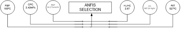
4. Aromatics are left essentially unchanged. Reactions leading to the formation of undesirable products include: 1. Dealkylation of side chains on naphthenes and aromatics form butane and lighter paraffin 2.Cracking of paraffin and naphthenes to form butane and lighter paraffin as the catalyst ages, it is necessary to change the process operating conditions to maintain the reaction severity and to suppress undesired reactions. There are four major reactions that take place during reforming: (1) dehydrogenation of naphthenes to aromatics, (2) dehydrocyclization of paraffin to aromatics, (3) isomerization, and (4)hydrocracking ANFIS is a five layers adaptive network-based fuzzy inference system offered by Jang [16]. As the name suggests, (ANFIS) models are a structure which can be fixed to behave such a physical system. This is especially beneficial when modeling nonlinear systems according to the experimental data is not available, accordingly when the process variable needed is not ready for physical modeling. This is, for instance, the case for the reformer system where the temperature of the reformer casing is available but not the temperature of the reformer bed itself. The models have the further benefits which are fast evaluating and would be studied online in control process systems or in larger models offline for investigation purposes. The FIS is included of three components: (1) a rule base, (2) a database and (3) a reasoning mechanism and operation. The rule base comprises of a choice of fuzzy rules. The database assigns the MFs that are applied in the fuzzy rules. The reasoning mechanism and it infers from the rules and input data to come to a practical outcome. These intelligent systems are a combination of procedures, knowledge and operations from different sources. The ANFIS identifies templates and assists in the revision of environments. FIS in MATLAB is employed in the whole process of the FIS evaluation and training. In this research, as it the ANFIS structure was used for a system with six inputs, one output and two membership functions. Figure 3 indicates all inputs parameters in the ANFIS selection techniques.
Data from a live unit (690) were introduced as main data for ANFIS structure training; then 46 individual data were used to test the obtained model. The fuzzification layer is the first layer where the inputs, in this case the FBP, CPC, RGF, RIT, CC and H2/HC are converted to fuzzy variables, which are numbers between zero and one. The membership layer is located in the second layer. It seems for the weights of every membership function. This layer takes the receiving signals from the former layer and next it acts as membership function to the representation of the fuzzy sets of each input respectively. The second layer nodes are non-adaptive.
The layer operates as a multiplier for receiving signals and sends the outcome in wi_=µ_AB(x)×µCD(y) form. Every output node shows the firing strength of a principle. The next and third layer is known as the rule layer. All neurons here act as the pre-condition matching the fuzzy rules for example each rule’s activation level is calculated, whereby the number of fuzzy rules is equal to the value of layers. Each node computes the normalized weights. The nodes in the 3rd layer are also considered as a non-adaptive. Each node computes the quantity of the rule’s firing strength over the sum of all rules’ firing strengths in the form of Wi*= wi/ w1+w2 ,i=1,2. The outcomes are referred as a normalized firing strength.
The 4th layer is responsible for presenting the output values as a result of the inference of rules. This layer is also known as a defuzzification layer. Every 4th layer node is an adaptive node and have the node function_Oi_4 = wi*. f = wi*. (pix+qiy+ri).In this layer, the (pi_, q_i, r) is the variable set. The variable set is designed as the consequent factors.
The 5th and final layer is recognized as the output layer. It adds all the receiving inputs from the preceding layer. After that, it transfers the fuzzy classification outcomes into a binary (crisp). The single node of the 5th layer is non- adaptive. This node calculates the overall output as the whole sum of all receiving signals:
O_(1,i)=μAi (x),i=1,2 O(1,i)=μ_(Bj-2) (y),i=3,4 (1)
In the process of identification of variables in the ANFIS structures, the hybrid learning algorithms were applied. In the forward pass of the hybrid learning algorithm, functional signals go forward up to layer 4 and the consequent parameters are determined by the least squares estimation. In the backward pass, the error rates circulate backwards and the premise variables are updated by the gradient decreasing.
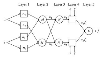
The ANFIS method was consist of the self-learning ability of neural network and the advantage of fuzzy inference which were able to approximate any linear or nonlinear systems. ANFIS was based on data sets rather than experiences or intuitions, in which the fuzzy rule and the membership function, were obtained by learning with the data sets. The typical structure of ANFIS is illustrated in Figure 4 [17]. The membership functions of one layer were the same (set the output of the layer of i as Ol,i), x and y are the inputs of the system and f is the output. The first layer: the input signals are fuzzified by the nodes in this layer:
O_(2,i)=ω=μ_Ai (x) μ_Bi (y),i=1,2 (2) (2)
where A/B are fuzzy sets, Ol,I is the membership function of the fuzzy sets, the default is bell-shape. The second layer: the output of this layer is the product of calculating the fitness of each rule:
O_(3,i)=ω ̅=ω/(ω_1+ω_2 ),i=1,2 (3) (3)
The third layer: normalize the fitness of each rule:
O_(4,i)=ω ̅f_i=ω ̅(p_i x+q_i y+r_i ),i=1,2 (4)
The fourth layer: calculate the output of each rule:
O_(5,i)=y=∑_i▒〖ω ̅f_i=(∑_i▒〖ω ̅f_i 〗)/(∑_i▒ω ̅ ),i=1,2〗 (5)
(5) The fifth layer: there is only one node in this layer which calculated the final output of the system. A hybrid algorithm which combined the black propagation and the test squares method was applied to train ANFIS, which was helpful for modeling of data sets.
Different membership functions (MFs) with various number of MFs was used in training, in order to reaching optimal ANFIS structure. Hybrid learning rule was adopted for training the model and then number of iterations was 500. The MSE was set as 0 and other parameters were left at their default values. ANFIS models were also programmed in the MATLAB 7.0 environment.
The main program of ANFIS model was as following: generation the initial ANFIS by mesh cutting method; train the model according to training data; input the testing data to the trained ANFIS and reaching the optimum output. Predicting the Octane Number with six inputs and one output, four different MFs were adopted and each types have different number of MFs from 2 to 6.
Results and Discussion
All data including DCS and Laboratory test has been extracted for two years from live CCR Unit at normal conditions. Optimised ANFIS model offered maximum RON Catalyst transfer rate, reactor inlet temperature, recycle gas flow rate, coke on catalyst and final boiling point were 987.24 Kg/hr, 527°C, 24.2 tonne/hr, 2.42wt% and 165°C, respectively. For achieveing the best model, the validity of data were confirmed during two years of operation. Figures 5-8 are shown the sensitivities of RON for mentioned factores in the CCR plant studies.
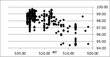
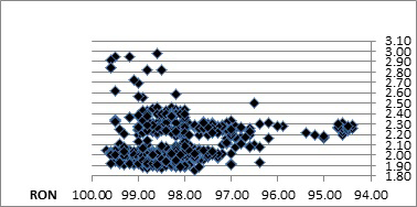
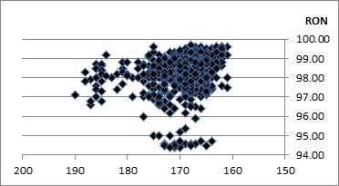
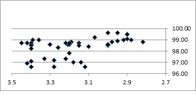
As observed in Figure5 the RON product was increased by increasing RIT of each reactors, and the average temperature was 522.2°C. The maximum and minimum temperatures were 527.01°C and 425.25°C, so its related RON was 97.1 and 99.7 respectively. The best value investigated is 527°C. In Figure 6, it has been cleared that H2/HC has no any effect on RON and the average, max and min were 1.86, 10.15 and 1.86 respectively. When FBP of feed was decreased, RON increased. The converting of linear molecular to aromatic was easier, so the min and max of FBP were at 161°C and 222°C respectively, which is clearly observed this effect on RON in Figure 7. Figure 8 is shown that when CPC wt% of catalyst increases and there is no any regeneration happened in the regeneration section, so RON decreases consequently.
Deactivation by coking is caused by high molecular weight carbon compound, which deposit at the pore entrance and lead to limit the diffusion of reactant and product.
Catalyst deactivation was occurred due to coke deposition increasing with temperature and decreasing of hydrogen partial pressure. Due to effect of coke on deactivation catalyst function, the min and max reached to 2.42 and 6.03 Wt% while the average was 3.7Wt%. The H2/HC ration is the mol ratio of pure hydrogen in the recycle gas to the feed flow rate. Hydrogen partial pressure is linked to the to the H2/HC ratio. Since is, in practice, little flexibility in the total pressure, hydrogen partial pressure is mainly adjusted through recycle flow. This ratio is essential for catalyst stability and effect of sweeping the reaction products and condensable materials from the catalyst and supplying the catalysts with readily available hydrogen. An increase in H2/HC ratio will move the naphtha through the reactors at a faster rate and supply a greater heat sink for the endothermic heat of reaction. A lower H2/HC ration decreases the hydrogen partial pressure and increase coke formation. Within the typical operating range, the H2/HC ration has little influence on product quality or yield.
Figure 9, displays increasing RGF rate lead to increase of RON, because more hydrogen causes less coke on catalyst, therefore the activity of catalyst keeps as well. In fact, increasing the recycle means that more H2 injected to the reactors, so that the hydro-cracking increases. Enhancing hydrocracker reactions in reforming reactors was increased the RON of products, and decreases the volume of products yield. The optimal point of RGF rate was 24.2 tonne/hr. As a whole, to evaluate the optimal determined point for the CCR plant, RIT for all reactors, FBP of feed, CPC, RGF rate and CC rate were manipulated from 527°C, 165°C, 2.42 Wt% and 24.2 tonne/hr to the estimated optimal point i.e 515°C, 212°C, 4.3 Wt%, 19.26 tonne/hand 981.24 Kg/hr, respectively. It was cleared that the actual RON of the CCR plant was enhanced from 99.2 to 99.7.
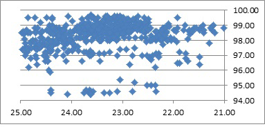
Figure 10 was shows that by increasing of RIT, rate of desired reactions, cyclization of linear component RON increases. By increasing CPC, the activity of catalyst begins to decrease gradually, so RON decrease. Following result extracted from ANFIS model diagram exactly match with DCS and Laboratory test, it means that selected model for artificial intelligence is correct. When inlet temperature of each reactor reach to 524°C and the rate of coke on catalyst reaches to 2.9 Wt%, Maximum of RON obtained (98.196).
It is impossible to touch less than mentioned percent of coke in the unit in two year data gathering. Because of some limitation for design of furnace, reaching to the more temperature is not possible. Almost at the overhaul time, obtaining to the more temperature than 519°C reactors inlet is not exist. Due to some bad operation of the upstream unit (NaphtaHydrotreater) FBP of feed increased (175°C), more FBP causes more coke on the catalyst (3.5wt%), so RON decreased to 95.732z.
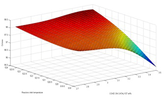
Figure 10 clearly illustrates that Increasing coke on catalyst causes decreasing catalyst activities. The polymerization of aromatic reformate or di-olefine was unsaturated by coke produces, as a result the active area, desired reaction decrease, produced LPG, light gas and olefin were decreased, respectively. An increase of the reactor inlet temperature results in:
An increased conversion of the non-aromatic compounds of the feed mainly the paraffins. Since the hydrocracking reaction is more favored than the cyclization of paraffins, in the total results RON was increased and yield decreased. An increase of the CPC which is compensated by a catalyst circulation increase to maintain at same level the coke content of the catalyst. Optimized rate to reach to the 99.7 RON were 527˚C and 2.42wt% for RIT and CPC, respectively. With increasing RIT, aromatic produced more and RON increased but yield of unit was decreased.
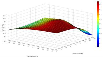
In Figure 11, when FBP of feed was increased, poly aromatic produced more and at high temperature poly aromatic converted to the Polymerization and produced coke then heavy hydrocarbon molecule creates and next coke produces easily in the reactor. Best RON achieved when FBP=165˚C and max coke= 3.26Wt% and RON decreased to almost 98.
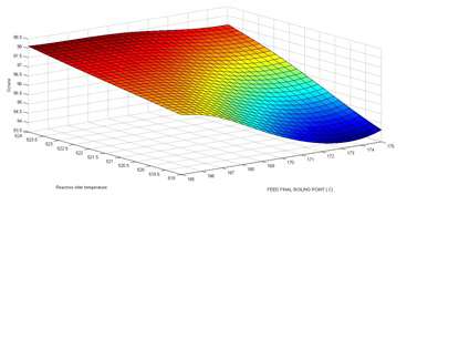
It can be seen that in Figure 12, the best RON achieved when FBP and RIT were 165ºC at 527˚C respectively.
To achieve this, the predictions’ per-formance of the ANFIS is compared with other well-known soft computing approaches including support vector machine (SVM) [18], artificial neural network (ANN) [19] and genetic programming (GP).
Conclusion
In this work, a commercial scale continuous catalytic reformer, as a key process for generating high octane gasoline, was simulated. Operating data and results were obtained from a commercial scale CCR unit during 2 years. In order to calibrate the simulator ANFIS method was used. An Adaptive Neuro-Fuzzy Inference System with fuzzy c-means clustering (FCM-ANFIS) was applied to model the RON prediction. Hybrid learning rule was adopted for training the model and the number of iterations was 500.Generating the initial ANFIS model was done by Cutting Method. Predicting RON was predicted with 6 inputs and one output. Four different MFs were adopted and each types had different number of MFs from 2 to 6.
Results showed that selected model is exactly match with the CCR unit. Achieved best operation data from model inter to the live unit with the capacity of 30000 bbl day -1. After validating the simulation and modeling, sensitivity analysis showed that the RON of product increased by elevating the RIT, but the yield of the gasoline product dropped. According to this analysis, the optimal RIT for all reactors, CC, FBP of the feed, RGF and CPC on catalyst were 527˚C, 987.24 kg/ hr, 165˚C, 24.86 tonne/ hr , 2.42 wt%, respectively. After applying these values in the live unit, gasoline octane number was increased from 99.2 to 99.7,and 640 bbl day-1 gasoline saved from this increasing of RON in final gasoline pool of refinery, also actual model and efficacy of the presented optimization approach was confirmed. Generally, there are many advantages in the use of the ANFIS scheme such as being adaptable for optimization and adaptive methods as well as being computationally efficient. ANFIS can be integrated with professional systems and rough sets for use in other applications. Systems that handle more complex parameters can also employ the use of ANFIS, as it is much faster compared to other control strategies.
References
-
Antos GJ, Aitani AM (2004) Catalytic Naphtha Reforming, Revised and Expanded. 2nd (Edn.), CRC Press, New York, USA.
-
Zahedi G, Mohammadzadeh S, Moradi G (2008) Enhancing Gasoline Production in an Industrial Catalytic- Reforming Unit Using Artificial Neural Networks. Energy & Fuels 22(4): 2671-2677.
-
Ancheyta-Juarez J, Villafuerte-Macias E (2000) Kinetic Modeling of Naphtha Catalytic Reforming Reactions. Energy Fuels 14(5): 1032-1037.
-
Mohammadi K, Shamshirband S, Lip Yee P, Mansor Z (2016) Using ANFIS for selection of more relevant parameters to predict dew point temperature. Applied Thermal Engineering 96(5): 311-319.
-
Rafiee-Taghanaki S, Arabloo M, Chamkalani A, Amani M, Adelzadeh MR, et al. (2013) Implementation of SVM framework to estimate PVT properties of reservoir oil. Fluid Phase Equilibria 346(25): 25-32.
-
Talebi R, Ghiasi MM, Talebi H, Mohammadyian M, Bahadori A, et al. (2014) Application of soft computing approaches for modeling saturation pressure of reservoir oils. Gas Sci Eng 20: 8-15.
-
Arabloo M, Rafiee-Taghanaki S (2014) SVM modeling of the constant volume depletion (CVD) behavior of gas condensate reservoirs. J Nat Gas Sci Eng 21: 1148-1155.
-
Ghiasi MM, Shahdi A, Barati P, Arabloo M (2014) Robust modeling approach for estimation of compressibility factor in retrograde gas condensate systems. Eng Chem Res 53(32): 12872-12887.
-
Navarro-Esbr J, Berbegall V, Verdu G, Cabello R, Llopis R (2007) A low data requirement model of a variable- speed vapour compression refrigeration system based on neural networks. Int J Refrig 30(8): 1452-1459.
-
Mohanraj M, Jayaraj S, Muraleedharan C (2012) Applications of artificial neural networks for refrigeration, air-conditioning and heat pump systems—a review. Energy Rev 16(2): 1340-1358.
-
Eldon YLi (1994) Artificial Neural Networks and their Business Applications. Information & Management 27(5): 303-313.
-
Atmaca H, Cetisli B, Yavuz HS (2001) The ANFIS as a Prediction Method of Efficiency of PV Cells. Electrical and Electronics Engineering Papers ELECO: 1389-1391.
-
Yang L, Entchev E (2014) Performance prediction of a hybrid microgeneration system using Adaptive Neuro- Fuzzy Inference System (ANFIS) technique. Appl Energy 134(1): 197-203.
-
Justesen KK, Andreasen SJ, Sahlin SL (2015) Modeling of a HTPEM fuel cell using Adaptive Neuro-Fuzzy Inference Systems. Hydrogen energy 40(46): 16814-16819.
-
Abdulshahed AM, Longstaff AP, Fletcher S, Myers A (2015) Thermal error modelling of machine tools based on ANFIS with fuzzy c-means clustering using a thermal imaging camera. Applied Mathematical Modeling 39(7): 1837-1852.
-
Jang JSR (1993) ANFIS: adaptive-network-based fuzzy inference system. IEEE transactions on systems, man, and cybernetics 23(3): 665-685.
-
Guler I, Ubeyli ED (2005) Adaptive neuro-fuzzy inference system for classification of EEG signals using wavelet coefficients. J Neurosci Methods 148(2): 113-121.
-
Vapnik VN (1998) Statistical Learning Theory. Wiley, New York 2: 421-445.
-
Schalkoff RJ (1997) Artificial Neural Networks. McGraw- Hill Higher Education, New York, London, pp: 56-94.
- Nigeria’s Vulnerability in the Face of Global Energy Policy
- A Simulation Study of Investigation of Optimum Oil Production Performance by Applying Various Gas Injection Methods in Oil Reservoir
- Characterization of Permo-Triassic Reservoirs through Thermal Maturity Assessment of Westphalian Source Rocks in the Cheshire Basin
- Influence of Microwax on the Rheological and Thermal Behaviour of a Wax Crude Oil
- Real-Time Monitoring and Performance Optimization of Steam Injection in Heavy Oil Reservoirs Using Fiber Optic Sensing and Integrated Predictive Simulation Models
- Rapid On-Site Determination of the Total Petroleum Hydrocarbon Content of Soils by Handheld Fourier Transform Near-Infrared Spectroscopy: Development of a Global, Site- and Scanner- Independent Calibration Model