Analyzing the Effects of Drillstring Speed on Bottom Hole Assembly Vibration in S-Shape Directional Wells: A Comprehensive Sensitivity Analysis
The main objective of this article is to do a comprehensive sensitivity analysis so as to study the influence of rotational speeds on the drillstring and BHA vibrations in well ZB-290 of s-shape well profile. This study is an extention of our reseach work of drillstring vibrations that were previously implemented to identify, analyze and control the resulting vibration in Zubair field wells. This well (ZB-290) has been drilled in Zubair field. Furthermore, recorded time-based vibration data and the vibration logs of this well to perform this analysis. BHAs forces, stresses, displacements, torque, and moments have been successfully identified and analysed taking into account the change of drilling speed. Drilling performance and future well designs will be enhanced based on the previous and this work.
Introduction
Due to the random nature of multiple components, including bit/formation contact, drillstring/borehole interaction, and hydraulics, drillstring vibrations are incredibly complicated. They contain a wide variety of phenomena, which makes the analysis rather difficult. Drilling may cause vibration in three different ways: axial, torsional, and lateral. These modes are accompanied by the phenomena bit bounce, stick/slip, and spinning, respectively. External excitations like bit/formation contact can cause drillstring vibrations [1, 2]. In these circumstances, changing the excitation source to the drillstring assembly’s or its component’s native frequency might result in harmful movements. Additionally, self-excited vibrations are present underground [1, 3]. The flow in the drillstring annulus may also cause vibrations [1, 4]. Dynamic systems can be either transient (unsteady state) or steady state (static).
The various assembly components may experience premature wear and damage as a result of drillstring vibrations, and the rate of penetration (ROP) decreases as a result because some of the drilling energy required to cut the rock is lost in vibrations. Additionally, vibrations may interfere with instruments used for measurement while drilling (MWD). Finally, vibrations frequently cause wellbore instabilities that can aggravate the well’s state and impair directional control as well as the wellbore’s general quality [1].
Therefore, sensitivity analysis is done in order to show the impact of drillstring speed on its bottom hole Assembly
(BHA) vibration analysis. Previously, to determine the sorts of vibrations that occurred in each well and each run, their sources, their severity, and the best mitigation strategies for each well, a diagnostic-analysis study was conducted and published in RJPGT. Additionally, these vibrations are graded and categorized to establish the level of severity of each run in drilled wells. In order to forecast the optimal drilling parameters for next operations, drilling parameters are also displayed and their trend lines are generated. Here, our work is to continue this research work and study the impact of various drillstring speeds on the vibrations’ analysis. To do this work, we will firstly review previous studies and simulation models. After that a field description will be also presented.
Background Studies
Drillstring vibrations have been extensively studied since several long years. A lot of authors and textbooks have presented several studies, simulations, developed models so as to measure or detect, model, simulate, and control the vibrations resulting from running the drillstring into the wellbore. Here, Table 1 shows a literature reviews of most of previous studies, published articles and techiques.
| Year | Author (s) | Study, Method, Technique, Approach, or Model |
|---|---|---|
| 1960 | Finnie & Bailey [3] | Describing the apparatus that has been created to experimentally detect axial force, torque, and axial and rotational movements at the top of a drill string. |
| 1968 | Huang & Dareing [5] | Addressing the drill pipe’s lateral vibrations and buckling. |
| 1981 | Millheim & Apostal [6] | Reporting on how BHA dynamics affect a bit’s trajectory is a part of an ongoing project to create a computer model that replicates the bit’s 3D travel. |
| 1984 | Dareing [7] | Giving advice for reducing severe drill string vibrations and explaining their sources. |
| 1985 | Wolf, et al. [8] | Presenting field data of downhole drillstring vibrations and quickly going through the relationship between downhole longitudinal and lateral vibrations and formation properties. |
| 1987 | Mitchell & Allen [9] | Providing 8 case studies of real BHA failures where the model predicted lateral vibrations with critical rotation speeds that nearly match the operational parameters at the moment of failure in all the analyzed BHAs. |
| 1987 | Skaugen [10] | Employing a drillstring dynamic model that operates in the time domain to examine how quasi-random drill bit vibrations affect drillstring dynamic behavior. |
| 1990 | Vandlver, et al. [11] | Describing the drill-collar spinning and the linear connection between WOB variations and the bending vibration of an originally curved BHA as the two main causes of the two case studies of BHA bending vibration. |
| 1990 | Rector III [12] | Demonstrating the use of downhole seismic sources created by drill-bit vibrations. |
| 1990 | Wang [13] | Investigating the impact of the lowing drilling fluid on drill stem stability and lateral vibration. |
| 1991 | Rector III & Marion [14] | Describing a novel wellbore seismic approach that makes advantage of the vibrations a drill bit produces during drilling as a source of downhole seismic energy. |
| 1998 | Dunayevsky & Abbassian [15] | Considering three basic mechanical systems that describe string torsional vibration, bit lateral dynamics, and coupled torsional-lateral vibration allows us to better understand the dynamic stability of PDC bits under induced torsional and lateral vibrations. |
| 1998 | Macpherson, et al. [16] | Analyzing drilling vibration data that was collected during a field test using both down-bole and surface vibration measuring equipment. |
| 2000 | Baumgart [17] | Employing nonlinear differential equations of motion for the longitudinal, lateral, and rotational motion of the pipe as well as for the rate of flow and pressure of the mud, one may develop and numerically solve a mathematical model as an initial value issue for the drilling procedure. |
| 2001 | Yigit & Christoforou [18] | Presenting an active control method for stick-slip vibrations together with a fully linked model for axial, bending, and torsional vibrations. |
| 2001 | Liu & Huang [19] | Establishing the vertical, lateral, and torsion coupled vibration of full-hole drilling strings and its solution for the lateral vibration dynamic model of roller cone rock bit. |
| 2002 | Chen, et al. [20] | Showing a field examination of the impact of lateral, spin, and stick-slip vibrations on roller- cone bit performance |
| 2003 | Al-Hiddabi, et al. [21] | Utilizing a non-linear dynamic inversion control design strategy to reduce a non-linear drillstring’s lateral and torsional vibrations. |
| 2005 | Pan, et al. [22] | Highlighting and summarizing the use of computational fluid dynamics methods in the investigation of vortex-induced vibration of maritime structures, as well as its hotspots and advancement. |
| 2005 | Cobern & Wassell [23] | Putting an active drilling vibration monitoring and control system through laboratory testing. |
| 2006 | Yigit & Christoforou [24] | Showing stick-slip and bit-bounce interactions in oil well drillstrings, by developing a straightforward model that accurately captures the dynamics and simulates the impacts of changing operating circumstances on stick-slip and bit-bounce interactions. |
| 2009 | Shi, et al. [25] | Designing and controlling the theory of the sidetrack horizontal well and branch wellbore trajectory. |
| 2010 | Reckmann, et al. [26] | Establishing a connection between MWD or LWD tool failure and downhole drilling dynamics in order to lower failure rates and expenses. |
| 2010 | Bailey & Remmert [27] | Controlling drilling vibrations through BHA design optimization to considerably improve performance and find ideal rotary-speed “sweet spots”. |
| 2010 | Wassell [28] | Describing a technique for evaluating vibration damage accumulation in drilling tools and setting vibration limits. |
| 2011 | Pavković, et al. [29] | Suggesting a torque estimator-based control technique with an auto-tuning algorithm for active dampening of torsional vibrations in oil well drill strings. |
| 2012 | Zhu, et al. [30] | Developing a down-hole measuring device that, when used for deepwater top-hole drilling, can measure annulus pressure, drill pipe pressure, and bottom hole temperatures in real- time. |
| 2012 | Kreuzer & Steidl [31] | Demonstrating the use of traveling wave decomposition to control the torsional vibrations of drill strings. |
| 2013 | Yang, et al. [32] | Demonstrating the development of MWD equipment and its study. |
| 2013 | Patil & Teodoriu [33] | Comparing various methods of simulating, regulating, and conducting laboratory-based experiments using torsional vibrations. |
| 2014 | Zhu, et al. [34] | Covering the phenomena and modeling techniques of stick-slip vibrations, as well as providing an up-to-date overview of stick-slip vibration behavior in drillstrings. |
| 2015 | Ghasemloonia, et al. [35] | Presenting an extensive literature review on drillstring vibration simulation. The current status of models for axial, torsional, and bending vibration prediction (uncoupled and coupled), boundary condition assumptions, equation formulation techniques, and applications to vibration mitigation are examined. Additionally, the difficulties of simulating drillstring vibration in the presence of contemporary drilling methods including deviated drilling and the usage of vibrating downhole instruments are covered. |
Table 1: Literature review study.
Drillstring Vibrations: Theory and Types
It has long been known that drill collars and nearby drillpipes are the parts that are subjected to the most hazardous vibrations. As a result, the BHA not only affects the assembly’s overall dynamic response, but it also serves as the site of the majority of failures. Therefore, comprehension of the BHA’s dynamic behavior is necessary for vibration mitigation. However, it should be noted that downhole vibrations can be a useful source of data that sheds light on bit wear, formation characteristics, and drillstring/wellbore interactions. They may potentially be employed as a possible seismic source, according to some research. Additionally, drillstring vibrations have been thought of as a way to improve drilling efficiency by boosting the power available to the bit [1, 2].
Due to the random nature of multiple components, including bit/formation contact, drillstring/borehole interaction, and hydraulics, drillstring vibrations are incredibly complicated. They contain a wide variety of phenomena, which makes the analysis rather difficult. Drilling can cause vibration in three different ways: axial, torsional, and lateral. These modes are accompanied by the phenomena bit bounce, stick/slip, and whirling, respectively [1, 2, 4, 15].
**Axial Vibration Model**
The undamped classical wave equation is expressed as follows:
$$\frac{\partial^2 \xi(x,t)}{\partial x^2} = \frac{1}{c^2} \frac{\partial^2 \xi(x,t)}{\partial t^2}$$
(1)
The general solution of the above equation including the superposition of terms is expressed in the following form:
$$\xi_n(x,t) = \left( A_n \sin \frac{\omega_n}{c} x + B_n \cos \frac{\omega_n}{c} x \right) \left( C_n \sin \omega_n t + D_n \cos \omega_n t \right), n=1,2,\ldots$$
(2)
Where $x$ refers to distance/or the beam axis, and $t$ refers to time. Also, the axial wave velocity is expressed as follows:
$$c^2 = \frac{E}{\rho}$$
(3)
Where $E$ is the Young modulus and $\rho$ is the material density.
The motion equation of the axial drillstring vibrations taking damping and external forces into account is expressed as follows:
$$\rho \frac{\partial^2 \xi}{\partial t^2} + c_a \frac{\partial \xi}{\partial t} - E \frac{\partial^2 \xi}{\partial x^2} + \rho g_z = g_a \left( x,t, \xi, \frac{\partial \xi}{\partial x}, \frac{\partial \xi}{\partial t} \right)$$
(4)
Where $C_a$ is a damping factor, $g_z$ is the acceleration gravity, and $g_a$ is the external axial force/unit mass affecting on the drillstring.
Bit bounce: The radial variation considering the coupling of axial and torsional vibrations of the drillstring BHA and with establishing the surface continuity in its center, is expressed as follows:
$$S(r,\phi) = S_n \sin \left( \frac{r}{\Delta r_b} \frac{\pi}{2} \right) \sin (3\phi), 0 \leq r \leq \Delta r_b \text{ and } 0 \leq \phi \leq 2\pi$$
$$S_o \sin \left( \frac{r}{\Delta r_b} \frac{\pi}{2} \right) \sin (3\phi), \Delta r_b \leq r \leq r_b$$
(5)
Where $r_b$ is the wellbore radius, $\Delta r_b$ is a smaller radius than $r_b$, and $r$ & $\phi$ are the radial and angular coordinates.
**Torsional Vibrations**
The torsional behavior of the assembly is expressed as follows:
$$\rho J \frac{\partial^2 \phi}{\partial t^2} - JG \frac{\partial^2 \phi}{\partial x^2} = g_T \left( x, \phi, t \right)$$
(6)
Where $J$ is the polar moment of inertia, $\phi$ is the angular displacement of the BHA, $G$ is the shear modulus of material, $g_T(x,0,t)$ is the torsional applied load, and $JG$ the product represents the torsional stiffness.
Stick/Slip Model: The equation of motion for this model when the rotary table moves at surface with constant speed, is expressed as follows:
$$I \dot{\phi} + c_r \dot{\phi} + F(\dot{\phi}) + k \phi = k \dot{U} t$$
(7)
Where $c_r$ is the coefficient of viscous damping, $k$ is the torsional stiffness of the drillstring, $I$ is the mass moment of inertia with respect to the rotation axial, and $F(\phi)$ is the friction induced forces.
Lateral Vibrations: The Euler-Bernoulli equation taking the axial forces effect into consideration with differential equations is expressed as follows:
$$\rho \frac{\partial^2 \phi}{\partial t^2} - \frac{\partial^2 \phi}{\partial x^2} \left( EI_z \frac{\partial^2 u}{\partial x^2} \right) = g(x,t)$$
(8)
$$\rho \frac{\partial^2 u}{\partial t^2} + \frac{\partial^2 \phi}{\partial x^2} \left( EI_z \frac{\partial^2 u}{\partial x^2} \right) - P \frac{\partial^2 u}{\partial t^2} = g(x,t)$$
(9)
Where $u(x,t)$ is the lateral displacement, $\rho$ is the mass density, $E$ is the modulus of elasticity, $Iz$ is the moment of inertia, and $g(x,t)$ refers to the external load.
**Whirling Model**
Equations of motion considering the RPM as a constant for a point equidistant located between two stabilizers are presented as follows:
$$ m \ddot {y} + c _ {w} \dot {y} + k _ {w} y = m e _ {0} \mathrm {U} ^ {2} \cos (\mathrm {U} t) \tag {10} $$ ( ) $$ m \ddot {z} + c _ {w} \dot {z} + k _ {w} y = m e _ {0} \mathrm {U} ^ {2} \sin (\mathrm {U} t) \tag {11} $$ ( ) Where e0 is the eccentricity of the center of mass cw is the damping coefficient kw is the lateral stiffness of collar m is the mass of DC y & z are the lateral coordinates Ω is the drillstring rotational speed
Field Data Description
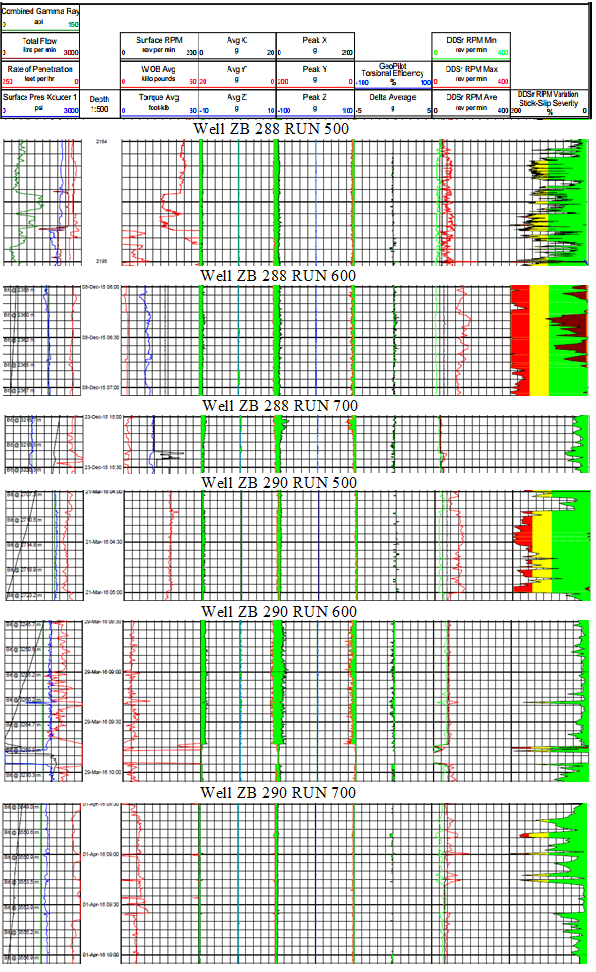
One of the onshore oil reservoir fields is called Zubair field, and it is situated in southern Iraq. Figure 1 depicts a map of the producing zones, including the third and fourth pay zones and their drilled wells, as well as a structural contour map. The reference wells for the production expectation for well ZB-398 Dir (proposed) in the third pay zone reservoir are ZB-283, ZB-325, ZB-078, ZB-116 as oil producers and injectors, and ZB-278 and ZB-210 as water injectors. The reference well for ZB-385 Dir (new) production expectation in the fourth pay zone reservoir, however, is ZB-200. The company’s long-term goals include expanding into new markets and boosting output. The current plans, however, represent a development strategy. It is consequently intended to drill three development wells to improve oil output from the Zubair field reservoir’s third pay zone. The third pay zone is being produced by 14 wells. The three to be drilled wells are designated ZB-390, ZB-391, and ZB-398. The vibration logs are accessible for six wells: ZB-288, ZB-290, ZB-295, ZB-311, ZB-349, and ZB-367, and time- based vibration data are collected. For each well, three runs of vibration logs are recorded ZB 288 runs: 500, 600, and 700; ZB 290 runs: 500, 600, and 700; and ZB 295 runs: 400, 500, and 600.
Wells ZB 311 and 349 run at 400, 500, and 600, respectively, whereas well ZB 367 runs at 300, 400, and 500. Tables 3 & 4 display the depth interval for each run for each well. The combined gamma ray, total flow, ROP, surface pressure, surface rotary speed, average WOB, average torque, lateral vibrations (Avg X and Avg Y), axial vibrations, DDSr RPM Variation, and other recorded data are all included in the vibration logs displayed in Figure 2. There have been more explanations and information published about this field [36, 37, 38]. Figure 1-b shows the s-shape profile with details of well ZB-290 and the necessary BHA for drilled 8 1/2” hole section appeared in Table 2.
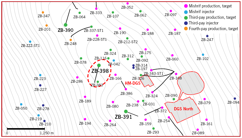
Figure 1a: Zubair field with its wells [36].
| Description | OD (in) | ID (in) | MaK OD (in) | Bottom Conn. | Top Conn. | Length (m) | Cumulative Length (m) | |
|---|---|---|---|---|---|---|---|---|
| 1 | 8 1/2” PDC bit | 8.5 | - | 8.5 | 4 1/2” REG B | 0.28 | 0.28 | |
| 1 | 7” SperryDrill Lobe 7/8 - 7.5 stg, STB sleeve 8.125, BH 1.22° | 7 | 4.95 | 8.25 | 4 1/2” REG B | 4 1/2” 1F B | 9.31 | 9.59 |
| 1 | Float Sub | 6.8 | 2.75 | 6.8 | 4 1/2” IF P | 4 1/2” 1F B | 0.82 | 10.41 |
| 1 | 7 5/8” Stabilizer | 6.8 | 2.81 | 7.625 | 4 1/2” IF P | 4 1/2” 1F B | 1.57 | 11.98 |
| 1 | 6 3/4” OM COLLAR | 6.75 | 3.13 | 6.75 | 4 1/2” IF P | 4 1/2” 1F B | 2.8 | 14.78 |
| 1 | 6 3/4” DGR COLLAR | 6.75 | 1.92 | 6.75 | 4 1/2” If P | 4 1/2” If B | 1.96 | 16.74 |
| 1 | 6 3/4” EWR-P4 COLLAR | 6.75 | 2 | 6.75 | 4 1/2” IF P | 4 1/2” 1F B | 3.66 | 20.4 |
| 1 | 6 3/4” HCIM COLLAR | 6.75 | 1.92 | 6.75 | 4 1/2” IF P | 4 1/2” 1F B | 1.45 | 21.85 |
| 1 | 6 3/4” BAT COLLAR | 6.75 | 1.91 | 6.75 | 4 1/2” IF P | 4 1/2” 1F B | 6.74 | 28.59 |
| 1 | 6 3/4” TM COLLAR | 6.75 | 3.13 | 6.75 | 4 1/2” IF P | 4 1/2” 1F B | 3.04 | 31.63 |
| 12 | 5” HWDP | 5 | 3 | 5 | 4 1/2” IF P | 4 1/2” 1F B | 112.32 | 143.95 |
| 1 | 6 1/2” DJ | 6.5 | 2.5 | 6.5 | 4 1/2” IF P | 4 1/2” I F B | 6.47 | 150.42 |
| 9 | 5” HWDP | 5 | 3 | 5 | 4 1/2” IF P | 4 1/2” I F B | 84.29 | 234.71 |
Table 2: Directional BHA for 8 ½” hole section (3190m-3559m).
![Figure 2: There have been more explanations and information published about this field [36- 38]. Figure 1-b shows the s-shape profile with details of well ZB-290 and the necessary BHA for drilled 8 1/2” hole section appeared in Table 2.](/fulltextimages/9899/fig_2.png)
Figure 1b: Well ZB-290 profile S-shape with all drilled section.
Study Results and Analysis
It is obvious that the various kinds of drilling vibrations have a significant influence on drilling performance and lengthen non-productive time. As a result, the non- productive cost will go up. There are six Zubair fields drill wells here (Figure 1) with vibration data shown Figure 2. ZB-288, ZB-290, ZB-295, ZB-311, ZB-349, and ZB-367 are the wells in question. Previously, vibration logs and drilling parameters were used to identify and evaluate the vibrations caused by the drillstring of Zubair field wells. Following the identification of the various vibration mode types and their associated sources, proposed mitigation measures are given. Additionally, these vibrations are graded and categorized to establish the level of severity of each run in drilled wells. Here, we present only the results of well ZB-290 which will be used in our work in this paper. Tables 3 & 4 show the diagnostic analysis of recoded vibrations, their modes and the required control methods.
| Value (RPM) % | Stick-Slip (RPM)% (RUN) | Level | State | Depth (M) | Limit Time | |
|---|---|---|---|---|---|---|
| 160-200 | >100 (500) | Severe | Stick-slip | 2707-2723 | Immediately reduce vibration | |
| ZB 290 | 20-40 | 0~40 (600) | Low | - | 3245-3270 | NO |
| 80-120 | 80~100(700) | High | Stick-slip | 3549-3556 | Must reduce vibration 30 minutes |
Table 3: Diagnostic and vibrations analysis of data recorded in 6 Zubair wells [38].
| Value | Avg X(g) | Avg Y(g) | Avg Z(g) | Peak X(g) | Peak Y(g) | Peak Z(g) | Formal & Types | Action | Signs of Success | |
|---|---|---|---|---|---|---|---|---|---|---|
| 290 Run 500 | RANG | 0-20 | 0-20 | 0-(10/-10) | 0-200 | 0-200 | 0-(100/-100) | Stick Slip (torsional vibration) | Reduce SWOB & increase RPM | Lower vibration |
| 290 Run 500 | MIN | 0.13 | 0.4 | 0 | 2.7 | 1.36 | 0 | Stick Slip (torsional vibration) | Reduce SWOB & increase RPM | Lower vibration |
| 290 Run 500 | MAX | 0.939 | 1.07 | 0 | 12.16 | 9.52 | 0 | Stick Slip (torsional vibration) | Reduce SWOB & increase RPM | Lower vibration |
| 290 Run 500 | >2 | >2 | >20 | >20 | >10 | Stick Slip (torsional vibration) | Reduce SWOB & increase RPM | Lower vibration | ||
| 290 Run 600 | RANG | 0-20 | 0-20 | 0-(10/-10) | 0-200 | 0-200 | 0-(100/-100) | Stick Slip (torsional vibration) | Reduce SWOB & increase RPM | Lower vibration |
| 290 Run 600 | MIN | 0.54 | 0.54 | 0 | 1.34 | 6.71 | 0 | Stick Slip (torsional vibration) | Reduce SWOB & increase RPM | Lower vibration |
| 290 Run 600 | MAX | 1.21 | 1.21 | 0.273 | 12 | 12.08 | 2.73 | Stick Slip (torsional vibration) | Reduce SWOB & increase RPM | Lower vibration |
| 290 Run 600 | >2 | >2 | >20 | >20 | >10 | Stick Slip (torsional vibration) | Reduce SWOB & increase RPM | Lower vibration | ||
| 290 Run 700 | RANG | 0-20 | 0-20 | 0-(10/-10) | 0-200 | 0-200 | 0-(100/-100) | Stick Slip (torsional vibration) | Reduce SWOB & increase RPM | Lower vibration |
| 290 Run 700 | MIN | 0.13 | 0.45 | 0 | 2.48 | 1.83 | 0 | Stick Slip (torsional vibration) | Reduce SWOB & increase RPM | Lower vibration |
| 290 Run 700 | MAX | 1.2 | 1.1 | 0.5 | 10.58 | 8.19 | 2.71 | Stick Slip (torsional vibration) | Reduce SWOB & increase RPM | Lower vibration |
| 290 Run 700 | >2 | >2 | >20 | >20 | >10 | Stick Slip (torsional vibration) | Reduce SWOB & increase RPM | Lower vibration |
Table 4: Identifying the drilling vibration modes and their mitigation ways for Zubair wells [38].
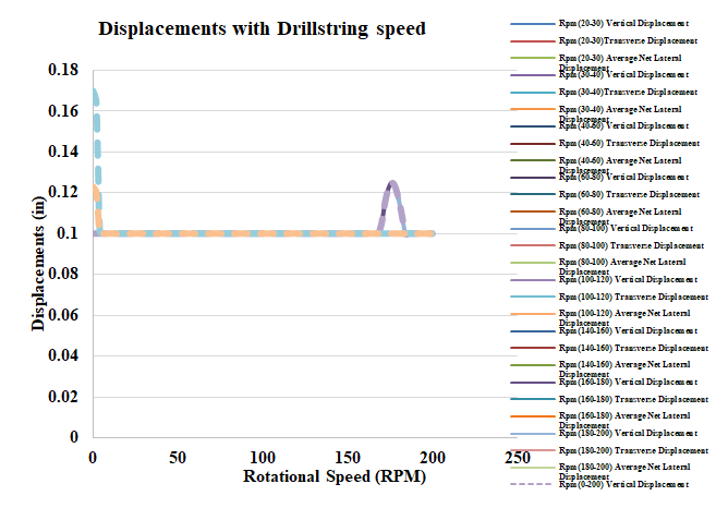
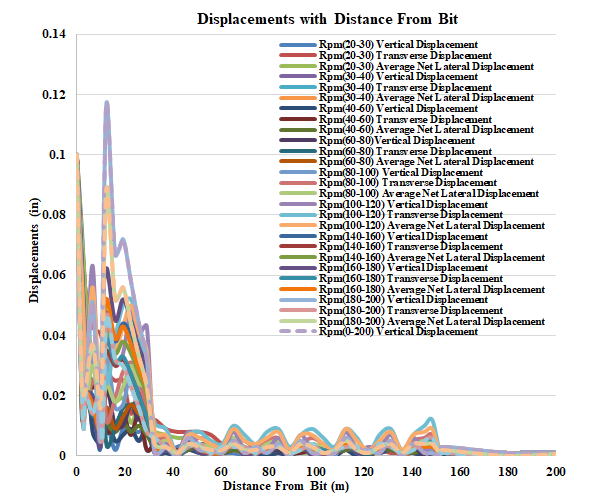
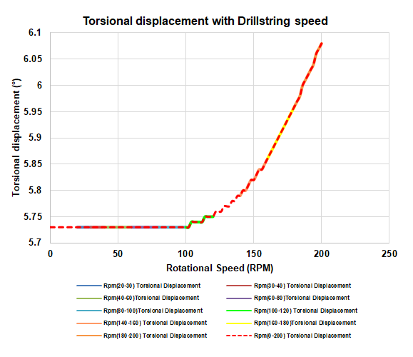
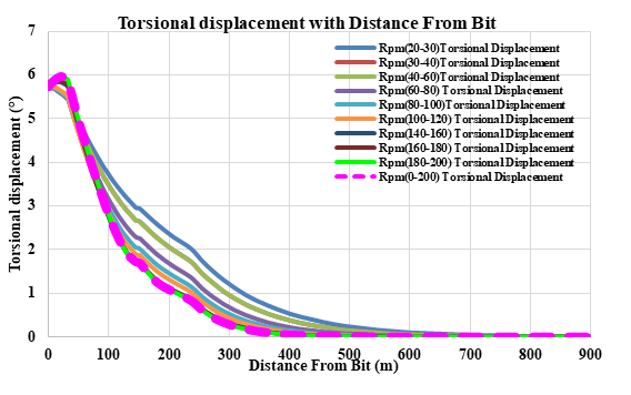
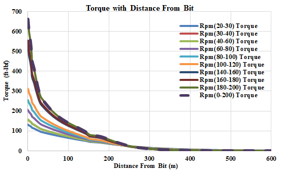
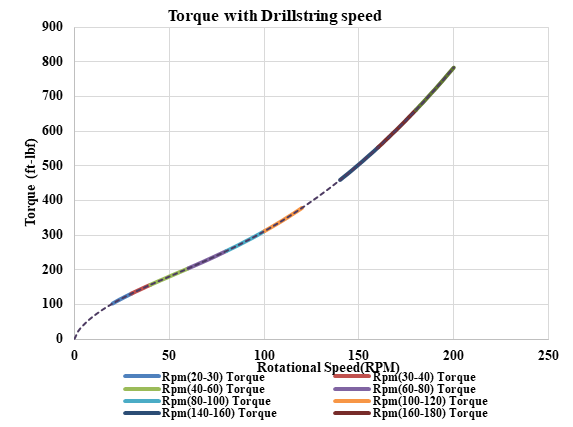
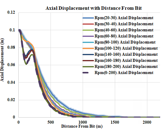
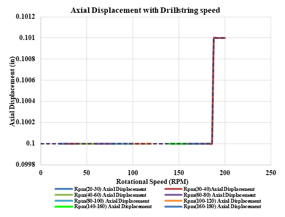
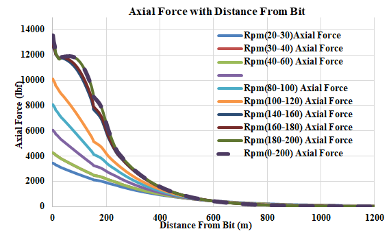
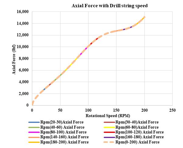
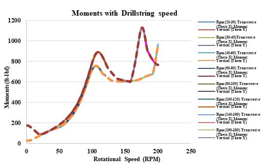
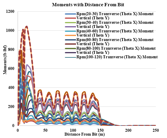
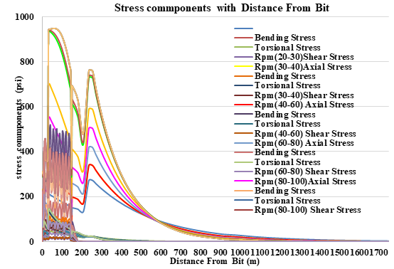
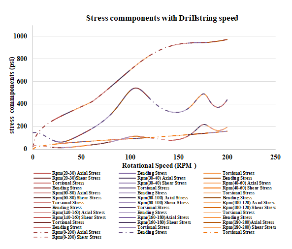
In this work, a sensitivity analysis study is done in well ZB-290 during drilling 8 1/2” hole section with directional BHA using Landmark software (Figures 1-b and Table 2) as shown in Figures 3 through 16. The study shows the impact of drillsting speed (RPM) on the BHA dynamics and vibration analysis. Firstly, the drillstring displacement shows higher values for lower speeds and 160-180 RPMs range (Figure 3) and show also higher values at shorter distances and higher rotational speeds (Figure 4). Figures 5 & 6 shows the torsional displacement from the bit with various RPMs. It’s clear that the more RPM, the higher torsional displacement appears after passing the speed of 100 RPM and in regard with the distance from the bit; the lower speed, the higher torsional displacement from the bit results. Then, the variation of torque for various RPMs shows an increasingly relationship i.e. the higher torque values achieve at higher rotational speed and at shorter distance from the bit (Figures 7 & 8). Furthermore, changing the RPM does not have any impact on the axial displacement until 180 RPM speed and this displacement appears with higher values at longer distance from the bit and decreases slowly with increasing the distance from the bit (Figure 9 & 10). This is due to the axial forces results at the same distances and behave like displacement change with the bit. Also, these forces rise with increasing the RPMs and vice versa (Figures 11 & 12). However, the variation of drillstring moments have a different behavior due to alteration of RPMs. Initially, their values increase with higher rotational speeds but values of 100-120 RPMs and 160-180 RPMs show an inclined higher values than normal trend. Additionally, shorter distance from the bit results in higher moments (Figures 13 &14). Finally, the stress components of BHA; which are bending, shear, torsional and shear; are gently rising with rotating the drillstring with higher RPMs. At short distance from the bit and at low RPMs, they appear lower stresses but the more RPMs, the higher stresses are results (Figures 15 & 16).
Conclusions
Based on the results and analysis, the following conclusions and recommendations are extracted:
- Sensitivity analysis is an important study showing the impact of any parameter on drilling performance and diagnosing the vibration modes and mitigation methods.
- RPM is a key-element in vibration analysis of the drillstring and BHAs.
- BHA dynamics and vibration analysis have been enhanced for Zubair wells.
- BHAs forces, stresses, displacements, torque, and moments have been successfully identified and analysed.
- This study adds a value in developing Zubair field and future wells.
- Drilling performance and future well designs will be enhanced based on the previous and this work.
References
-
Aadnoy B, Cooper I, Miska S, Mitchell RF, Payne ML (2009) Advanced Drilling and Well Technology. SPE, pp: 888.
-
Dunayevsky VA, Abbassian F, Judzis A (1993) Dynamic Stability of Drillstrings Under Fluctuating Weight on Bit. SPE Drill & Compl 8(2): 84-92.
-
Finnie I, Bailey JJ (1960) An Experimental Study of Drillsting Vibration. ASME, Journal of Engineering for Industry 82(2): 129-135.
-
Paidoussis MP, Luu TP, Prabhaker S (2007) Dynamic of a Long Tubular Cantilever Conveying Fluid Downwords, Which Then Flows Upwords Around the Cantilever as a Confined Annular Flow. Journal of Fluids and Structures 24(1): 111-128.
-
Huang T, Dareing DW (1968) Buckling and lateral vibration of drill pipe. J Eng Ind 90(4): 613-619.
-
Millheim K, Apostal MC (1981) The effect of bottomhole assembly dynamics on the trajectory of a bit. Journal of Petroleum Technology 33(12): 2323-2338.
-
Dareing DW (1984) Guidelines for Controlling DrillString Vibrations. J Energy Resour Technol 106(2): 272-277.
-
Wolf S, Zacksenhouse M, Arian A (1985) Field measurements of downhole drillstring vibrations. Proceedings of the SPE Annual Technical Conference and Exhibition, Society of Petroleum Engineers, Las Vegas, Nevada, USA.
-
Mitchell RF, Allen MB (1987) Case studies of BHA vibration failure. Proceedings of the SPE Annual Technical Conference and Exhibition, Society of Petroleum Engineers, Dallas, Texas, USA.
-
Skaugen E (1987) The effects of quasi-random drill bit vibrations upon drillstring dynamic behavior. Proceedings of the SPE Annual Technical Conference and Exhibition, Society of Petroleum Engineers, Dallas, Texas, USA.
-
Vandlver JK, Nicholson JW, Shyu RJ (1990) Case studies of the bending vibration and whirling motion of drill collars. SPE Drilling Engineering 5(4): 282-290.
-
Rector JW III (1990) Utilization of drill-bit vibrations as a downhole seismic source. PhD thesis, Stanford University, USA.
-
Wang Z (1990) Effects of the lowing drill fluid on lateral vibration and stability of the drill stem. China Petroleum Machinery 18(1): 31-36.
-
Rector JW III, Marion BP (1991) The use of drill-bit energy as a downhole seismic source. Geophysics 56(5): 628-634.
-
Dunayevsky VA, Abbassian F (1998) Application of stability approach to bit dynamics. SPE Drill & Compl 13(2): 99-107.
-
Macpherson JD, Jogi P, Kingman JE (1998) Application and analysis of simultaneous near bit and surface dynamics measurements. Proceedings of the IADC/SPE Drilling Conference, Dallas, Texas, USA.
-
Baumgart (2000) Stick-slip and bit-bounce of deep-hole drillstrings. Journal of Energy Resources Technology 122(2): 78-82.
-
Yigit S, Christoforou AP (2001) Active control of stick- slip vibrations: the role of fully coupled dynamics. Proceedings of the SPE Middle East Oil Show, Society of Petroleum Engineers, Manama, Bahrain, pp: 167-181.
-
Liu Q, Huang B (2001) Establishment of lateral vibration dynamic model of roller cone rock bit and its solution. Natural Gas Industry 21(4): 55-56.
-
Chen SL, Blackwood K, Lamine E (2002) Field investigation of the effects of stick-slip, lateral, and whirl vibrations on rollercone bit performance. SPE Drill & Compl 17(1): 15-20.
-
Al-Hiddabi SA, Samanta B, Seibi A (2003) Non-linear control of torsional and bending vibrations of oilwell drillstrings. Journal of Sound and Vibration 265(2): 401- 415.
-
Pan ZY, Cui WC, Zhang XC (2005) Overview on VIV of slender marine structures. Journal of Ship Mechanics 9(6): 135-154.
-
Cobernand ME, Wassell ME (2005) Laboratory testing of an active drilling vibration monitoring & control system. Proceedings of the AADE National Technical Conference & Exhibition, Houston, Texas, USA, pp: 5-7.
-
Yigit S, Christoforou AP (2006) Stick-slip and bit-bounce interaction in oil-well drillstrings. J. Energy Resour. Technol 128(4): 268-274.
-
Shi X, Yu Z, Chen P (2009) Design and Control Theory of the Sidetrack Horizontal Well and Branch Wellbore Trajectory. Petroleum Industry Press, Beijing, China.
-
Reckmann H, Jogi P, Kpetehoto FT, Chandrasekaran S, Macpherson JD (2010) MWD failure rates due to drilling dynamics. Proceedings of the IADC/SPE Drilling Conference and Exhibition, Society of Petroleum Engineers, New Orleans, La, USA, pp: 49-58.
-
Bailey JR, Remmert SM (2010) Managing drilling vibrations through BHA design optimization. SPE Drill & Compl 25(4): 458-471.
-
Wassell BS (2010) Method of establishing vibration limits and determining accumulative vibration damage in drilling tools. Proceedings of the SPE Annual Technical Conference and Exhibition, Society of Petroleum Engineers, Florence, Italy.
-
Pavkovi´c D, Deur J, Lisac A (2011) A torque estimator- based control strategy for oil-well drill-string torsional vibrations active damping including an auto-tuning algorithm. Control Engineering Practice 19(8): 836-850.
-
Zhu RD, Chen P, Zhou JL, Li X (2012) The development of a downhole tool used in deep water top hole drilling that can measure pressure and temperature while drilling. Machinery 1(1): 93-95.
-
Kreuzer E, Steidl M (2012) Controlling torsional vibrations of drill strings via decomposition of traveling waves. Archive of Applied Mechanics 82(4): 515-531.
-
Yang C, Chen P, Xia H, Han X, Ma T (2013) Progress in research and development of measurement-while- drilling apparatuses. Natural Gas Industry 33(2): 71-75.
-
Patil PA, Teodoriu C (2013) A comparative review of modelling and controlling torsional vibrations and experimentation using laboratory setups. Journal of Petroleum Science and Engineering 112: 227-238.
-
Zhu X, Tang L, Yang Q (2014) A literature review of approaches for stick-slip vibration suppression in oil well drillstring. Advances in Mechanical Engineering 6: 967952.
-
Ghasemloonia A, Geoff Rideout D, Butt SD (2015) A review of drillstring vibration modeling and suppression methods. Journal of Petroleum Science and Engineering 131: 150-164.
-
El Gaburi H, Halafawi M, Avram L (2020) Offset-well data improve Zubair wellbore stability. Oil and Gas Journal 118(1).
-
“Eni Consortium to Redevelop Zubair Field in Iraq”. RIGZONE.
-
Al Gburi H, Halafawi M, Al Gburi H, Avram L (2020) Dignostic and Performance Analysis of Drillstring Vibrations in Zubair Field. Romanian Journal of Petroleum and Gas Technology 72(2): 23-35.
- Nigeria’s Vulnerability in the Face of Global Energy Policy
- A Simulation Study of Investigation of Optimum Oil Production Performance by Applying Various Gas Injection Methods in Oil Reservoir
- Characterization of Permo-Triassic Reservoirs through Thermal Maturity Assessment of Westphalian Source Rocks in the Cheshire Basin
- Influence of Microwax on the Rheological and Thermal Behaviour of a Wax Crude Oil
- Real-Time Monitoring and Performance Optimization of Steam Injection in Heavy Oil Reservoirs Using Fiber Optic Sensing and Integrated Predictive Simulation Models
- Rapid On-Site Determination of the Total Petroleum Hydrocarbon Content of Soils by Handheld Fourier Transform Near-Infrared Spectroscopy: Development of a Global, Site- and Scanner- Independent Calibration Model