Role and Advancements in Geomechanical Challenges in Carbon Capture and Sequestration
Anthropogenic CO2 emissions rapidly increased during the post-industrial revolution causing global warming issues. In order to reduce the CO2 concentration in the atmosphere Carbon Capture and Sequestration will play a key transition role to transform into clean energy by utilizing the existing oil and gas infrastructure and subsurface data. The technology comes with certain challenges, amongst them, one of the real threats is the stored CO2 leakage back into the atmosphere and at shallower surfaces. This work talks about the understanding of geomechanical risks involved in the CCS process and probable ideas to mitigate the risks. CO2 injection leads to an increase in the pressure within the pores which eventually results in a change of stress and strain conditions within the reservoir. With a proper understanding of the reservoir and with a realistic field dataset a controlled injection can avoid a formation leading to geomechanical failures. Often field data are insufficient, in such a scenario this works talks about the preventive measures that can be adopted to avoid early mentioned calamity.
Introduction
Carbon dioxide is a primary contributor to greenhouse gas emissions. It can be stored in subsurface conditions within saline aquifers, as they are abundant and provides adequate capacity [1, 2]. However, this storage method is not foolproof; it comes with certain geomechanical challenges and risks. CO2 injection increases the pore pressure and can lead to caprock failure, reactivation of pre-existing faults, abnormal poroelastic response, surface uplift, induced seismicity contamination of drinking water, and soil pollution [3, 4]. To mitigate CO2 migration risk to shallower depths, understanding the lithostratigraphic context of the proposed repository, the state of stress and the reservoir geomechanics processes become important.
Fortunately, there is no report of significant carbon leakage from carbon sequestration since its inception in
1996 in the Sleipner oil field in the North Sea [5]. But low induced seismic risk remains one of the basic criteria for a carbon sequestration site selection. Carbon dioxide leakage potentials can be divided into two broad categories, (i) Leakage potential from abandoned wellbores and (ii) leakage potential from geological formation through weak planes. A poor abandoned well database possess a real threat in identifying potential leakage areas whereas, within geological formation fault geometry, the existence of blind faults, critically stressed faults and fractures adds computational expenses [6].
To efficiently understand the geomechanical risks, a multiscale model of the reservoir is essential [7]. Models such as the single-phase analytical model [8], hybrid analytical-2D numerical simulation model [9], fluid simulation model [7], geomechanical model [10] previously addressed the leakage issue along the fault paths. But, in recent years numerical modelling combined with reservoir flow simulation and geomechanical models achieved quite a success to predict rock failure behaviour under CO2 injection [4]. Coupled simulators such as TOUGH-FLAC3D [11, 12], GEM-COMSOL [13], Eclipse-VISAGE [14, 15], ABAQUS [16], plays a pivotal role in geomechanical application for carbon dioxide storage. However, the efficiency and accuracy of the model only increase with the valuable addition of field data.
Previous Studies
Change in pore pressure during gas and fluid storage modifies the magnitude of horizontal stresses leading to the potentially irreversible mechanical change within the in situ rock, increasing the possibility of injection-related seismicity, caprock failure, and reactivation of existing faults [17, 18, 19]. Detailed knowledge of pre-existing faults, fault slip potential, criteria for generation of new faults and fractures, local and regional stress regimes, and earthquake focal mechanisms contribute significantly to the geomechanical understanding of the reservoir subjected to injection [20, 21, 22]. Based on such valuable information, a comprehensive geomechanical model of a CO2 repository reservoir can be created. An accurate evaluation of the magnitudes, the direction of principal stresses, and pore pressure [23, 24] while creating the model can help understand the potential for unfavourable outcomes and thus guide operational outcomes as detected by sensor arrays for seismic surveys, deformation and induced seismicity.
Data Acquisition and State of Stress
Pore pressure data can be acquired from the Drill Stem Test, the Repeat Formation Test, borehole geophysical logs, seismic data, and drilling mud weight values [25, 26, 27]. The orientation of principal stresses is derived from borehole breakouts and tensile fractures, earthquake focal mechanisms [25, 28]. There are many methods and direct measurements to estimate the magnitude of the stresses such as density log data (for Sv magnitude), poroelastic horizontal strain model, empirical tectonic factors, image log data, borehole failure data, earthquake focal mechanism inversion technique (for Shmax magnitude) and specific activities such as Leak-Off Tests, Hydraulic Fracturing Tests and Pressure While Drilling, and Diagnostic Fracture Injection Test (for Shmin magnitude) [22, 27, 29, 30]. Based on the principal stress magnitude and directions, the state of stress can be specified and extrapolated regionally, given adequate data. In general, studies show that elevated compressive regional stress is more conducive to rock slip within a reservoir [31].
Identifying pre-existing faults, particularly critically stressed faults, is crucial to probabilistically analyze and assess reservoir containment before a major prolonged injection period. Providing that injection pressures do not exceed the minimum principal stress, rock commonly fails under shear failure and pre-existing faulted/fractured rocks require special attention in the framework of Mohr-Coulomb failure analysis [4]. Within the subsurface, fault specification (undetected faults, small faults, unknown lateral continuity of a fault system, fracture orientation) is needed. Then, pore pressures, local stress of faults, elastic properties and frictional/cohesive strength specification present real challenges. To quantify uncertainties, the probability of the fault plane slipping can be expressed as:
[ ] 0 fP =P n τ µσ − ≤ (1) [22]
Specifying Mohr-Coulomb failure criteria in a probabilistic manner, fault planes which are most susceptible to slip can be identified.
To avoid a fault plane slipping under shear failure, Ferronato, et al. [31] introduced a safety factor by which the threshold margin of injection pressure can be detected.
For shear failure a safety factor can be expressed as:
( ) * 1 / m m χ τ τ = − (2)
In which m τ is the current largest shear stress and * m τ is the maximum allowable shear stress.
For tensile failure safety factor is presented as:
3 3,0 σ σ Ψ = (3)
Where 3,0 σ is the initial minimum principal stress. When 0 Ψ = , tensile fracture is induced.
Changes in stress conditions can lead to the opening of microfracture networks, reactivate pre-existing faults, and create induced fracture, leading to micro-seismic risk to the formation [32]. Studying the change in stress path is an accepted method to identify the slip potential of the fault plane and determine allowable maximum injection pressure [19].
Possible Areas Undergoing Geomechanical Changes
Within a reservoir, there are areas more vulnerable to brittle deformations. Over-pressured zones have lower effective stresses and are more prone to slip, thus, requiring special consideration during injection simulation [4, 22]. Moreover, the lower boundary of the cap rock is the weakest zone to initiate a slip surface and this tendency is influenced also by the thermal expansion coefficient and elastic properties of the rock [4, 33]. Even sufficient temperature differences can cause fractures to develop within the caprock [34].
The distribution of injected CO2 is driven by heterogeneous permeability distributions in the subsurface [35]. Rutqvist, et al. [33] observed a proportional relation between permeability and the change in effective stress after the injection of CO2. Thus, it is essential to consider the various geomechanical factors together to provide realistic simulations and reliable probabilistic assessments.
Effective stress within the formation is reduced with the injection of CO2. This can lead rock to fail in three different ways:
- An immediate slip on the critically stressed planes under the influence of high pore pressure, especially in the areas close to the injection point, therefore further reducing the stress-bearing capacity.
- Modified stress magnitudes of much larger scale leading to the slip of distantly placed weak planes at roughly the same depth.
- Prolonged injection with an accumulation of additional stress triggering faults at different depths [36, 37, 38].
Geomechanical Simulation Studies
To ensure safe injection, reservoir simulation involving CO2 and brine flow coupled with geomechanics analysis provides a better estimation of the hydrofracturing and stick-slip threshold values as compared to single-phase flow models [21]. If the reservoir itself is faulted, it can be analyzed by the finite-thickness element approach [20]. However, knowledge of subsurface parameters is often somewhat sparse and not regularly distributed, thus a probabilistic approach is the best way to model the injection-related geomechanical changes and therefore outcomes. Such an approach can deal with stress magnitudes, the orientation of the principal stress, fault orientation and dip, and frictional coefficient-related uncertainties [36, 39]. Fluid flow coupled with geomechanical simulation (e.g., GEM-COMSOL, Eclipse- VISAGE, TOUGH-FLAC, ABAQUS) helps to identify the risks involved in the form of surface upliftment, induce seismicity, reactivation of faults, generation of new fracture networks.
With a probabilistic geomechanics approach, the San Juan CarbonSAFE project in the USA was identified as having low-induced seismicity potential [40].
With a controlled injection pressure, tensile failures can be avoided within the rock [32]. However, on the other hand, a tensile crack can appear under low differential stress conditions for critically-stressed faults and fractures which further decreases the value of the maximum allowable pressure of injection [41]. The rock’s mechanical strength and geometric characteristics can be comprised of the reaction of CO2 with minerals, leading to drastic changes in local stress conditions [42].
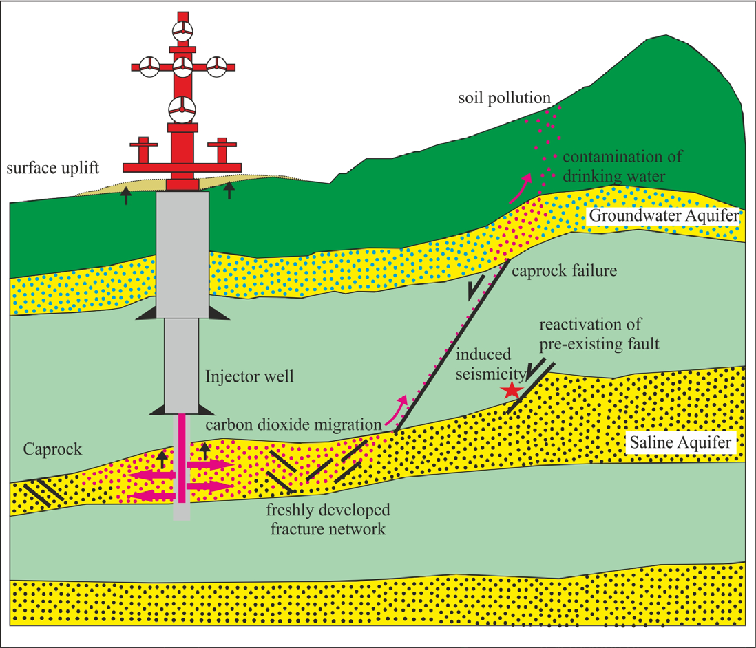
Figure 1: Conceptual diagram of CO2 leakage from geological storage under a high CO2 injection rate. The pink colour represents injected CO2. Black straight lines indicated weak planes (faults and fractures). Blue dotted circles indicate ground/ drinking water. Black solid arrows indicate surface upliftment. The black half arrow indicates the slip direction of the fault plane. The red star indicates seismic activity. Diagram not to scale.
Discussion
The CO2 storage project in In Salah, Algeria, was identified with injection-induced faulting. This is a classic case of fracture reactivation and the area is now identified with potential microseismic activity area [43]. Regular monitoring of CO2 injection not only helps to detect valuable information but also helps to initiate preventive measures against early warnings. Several monitoring methods such as geophysical survey (microseismic activity analysis), hydrogeochemistry and surface soil gas technique, and shallow well monitoring of underground fluids are capable of detecting CO2 leakage [44, 45, 46]. However, none of them is infallible. At Svelvik in Norway, a shallow-level (20m) CO2 injection test resulted in an unpredictable CO2 gas escape route, which further demands the improvement of existing fixed monitoring methods [45]. Carbon dioxide can leak at an uncontrollable rate under the existence of faults and fractures. In such a scenario, polymers, gels and foams can be used to choke porous and permeable zones and reduce fluid mobility [6]. Recently, the microbially induced carbonate precipitation (MICP) technique yielded a positive result in treating fractured concrete with a 26-50% recovery of the initial tensile strength [47]. With proper tuning, this method has the potential to become successful in treating densely induced fractured intervals. Although the preference should always be not to initiate fault and fracture networks by controlling the CO2 injection rate [48].
Conclusion
CO2 is one of the primary contributors as a greenhouse gas that can be stored in subcritical conditions within saline aquifers as they are abundant and provides more capacity. However, the storage method comes with certain geomechanical risks which need to be eliminated before identifying a reservoir as a suitable storage site. Such risks involve the reactivation of faults, creation of new fractured networks, induced seismicity, surface upliftment and migration of CO2 from the leaked path to shallower levels. This work reviews the recent advancements in geomechanical challenges in carbon capture and sequestration. Reservoir Modelling can only be performed close to reality with the availability of the field data. In case of the non-availability of the dataset, a probabilistic statistical approach can possibly be a good option to identify the leakage risks. With a close post-injection monitoring method, it is possible to identify an early indication of geomechanical failure. In case of a rock failure under injection pressure, there are methods that exist to choke or treat the fractured interval and help them recover their strength back.
References
-
Bergmann P, Lengler U, Schmidt-Hattenberger C, Giese R, Norden B, et al. (2010) Modelling the geoelectric and seismic reservoir response caused by carbon dioxide injection based on multiphase flow simulation: Results from the CO2SINK project. Geochemistry 70(3): 173- 183.
-
Bandilla KW, Celia MA, Birkholzer JT, Cihan A, Leister EC, et al. (2015) Multiphase modeling of geologic carbon sequestration in saline aquifers. Groundwater 53(3): 362-377.
-
Rutqvist J (2012) The geomechanics of CO2 storage in deep sedimentary formations. Geotechnical and Geological Engineering 30(3): 525-551.
-
Song Y, Jun S, Na Y, Kim K, Jang Y, et al. (2022) Geomechanical Challenges during Geological CO2 Storage: A Review. Chemical Engineering Journal 456: 140968.
-
Torp TA, Gale J (2003) Demonstrating storage of CO2 in geological reservoirs: the Sleipner and SACS projects. Greenhouse Gas Control Technologies-6th International Conference, Pergamon, Turkey, pp: 311-316.
-
Mortezaei K, Amirlatifi A, Ghazanfari E, Vahedifard F (2020) Potential CO2 leakage from geological storage sites: advances and challenges. Environmental Geotechnics 8(1): 3-27.
-
Tillner E, Kempka T, Nakaten B, Kühn M (2013) Brine migration through fault zones: 3D numerical simulations for a prospective CO2 storage site in Northeast Germany. International Journal of Greenhouse Gas Control 19: 689-703.
-
Zeidouni M (2012) Analytical model of leakage through fault to overlying formations. Water Resources Research 48(12).
-
Kang M, Nordbotten JM, Doster F, Celia MA (2014) Analytical solutions for two‐phase subsurface flow to a leaky fault considering vertical flow effects and fault properties. Water Resources Research 50(4): 3536- 3552.
-
Rinaldi AP, Rutqvist J, Cappa F (2014) Geomechanical effects on CO2 leakage through fault zones during large- scale underground injection. International Journal of Greenhouse Gas Control 20: 117-131.
-
Rinaldi AP, Rutqvist J, Finsterle S, Liu HH (2017) Inverse modeling of ground surface uplift and pressure with iTOUGH-PEST and TOUGH-FLAC: The case of CO2 injection at In Salah, Algeria. Computers & Geosciences 108: 98-109.
-
Rutqvist J (2011) Status of the TOUGH-FLAC simulator and recent applications related to coupled fluid flow and crustal deformations. Computers & geosciences 37(6): 739-750.
-
Khan S, Khulief YA, Al-Shuhail AA (2020) Effects of reservoir size and boundary conditions on pore- pressure buildup and fault reactivation during CO2 injection in deep geological reservoirs. Environmental Earth Sciences 79: 1-23.
-
Rahman MJ, Fawad M, Choi JC, Mondol NH (2022) Effect of overburden spatial variability on field-scale geomechanical modeling of potential CO2 storage site Smeaheia, offshore Norway. Journal of Natural Gas Science and Engineering 99: 104453.
-
Benisch K, Graupner B, Bauer S (2013) The coupled OpenGeoSys-eclipse simulator for simulation of CO2 storage–code comparison for fluid flow and geomechanical processes. Energy Procedia 37: 3663- 3671.
-
Karimnezhad M, Jalalifar H, Kamari M (2014) Investigation of caprock integrity for CO2 sequestration in an oil reservoir using a numerical method. Journal of Natural Gas Science and Engineering 21: 1127-1137.
-
Zoback MD, Zinke JC (2002) Production-induced normal faulting in the Valhall and Ekofisk oil fields. In The mechanism of induced seismicity, Birkhäuser, Basel, Switzerland, pp: 403-420.
-
Suhendi C, Sahara DP, Sule MR (2019) Modeling the behavior of CO2 injection in a sand reservoir. J Phys: Conf Ser 1204(1): 012089.
-
Radwan A, Sen S (2021) Stress path analysis for characterization of in situ stress state and effect of reservoir depletion on present-day stress magnitudes: Reservoir geomechanical modeling in the Gulf of Suez Rift Basin, Egypt. Natural Resources Research 30(1): 463-478.
-
Cappa F, Rutqvist J (2011) Modeling of coupled deformation and permeability evolution during fault reactivation induced by deep underground injection of CO2. International Journal of Greenhouse Gas Control 5(2): 336-346.
-
Tueckmantel C, Fisher QJ, Manzocchi T, Skachkov S, Grattoni CA, et al. (2012) Two-phase fluid flow properties of cataclastic fault rocks: Implications for CO2 storage in saline aquifers. Geology 40(1): 39-42.
-
Yaghoubi A, Dusseault MB, Leonenko Y (2022) Injection- induced fault slip assessment in Montney Formation in Western Canada. Scientific reports 12(1): 1-12.
-
Ganguli SS, Sen S, Dimri VP (2018) A comprehensive geomechanical assessment of an Indian mature oil field for CO2-enhanced oil recovery and its sequestration. In AGU Fall Meeting Abstracts pp: MR51B-0058.
-
Radwan AE, Abudeif AM, Attia MM, Elkhawaga MA, Abdelghany WK, et al. (2020) Geopressure evaluation using integrated basin modelling, well-logging and reservoir data analysis in the northern part of the Badri oil field, Gulf of Suez, Egypt. Journal of African Earth Sciences 162: 103743.
-
Yaghoubi A, Hickson CJ, Leonenko Y, Dusseault MB (2022) Probabilistic assessment of induced seismicity at the Alberta No. 1 geothermal project site. Canadian Journal of Earth Sciences 60(3): 294-306.
-
Zoback MD (2009) Reservoir geomechanics. Cambridge university press, California, USA.
-
Zhang J (2011) Pore pressure prediction from well logs: Methods, modifications, and new approaches. Earth- Science Reviews 108(1-2): 50-63.
-
Yaghoubi A, Mahbaz S, Dusseault MB, Leonenko Y (2021) Seismicity and the State of Stress in the Dezful Embayment, Zagros Fold and Thrust Belt. Geosciences 11(6): 254.
-
Taghipour M, Ghafoori M, Lashkaripour GR, Moghaddas HN, Molaghab A, et al. (2019) Estimation of the current stress field and fault reactivation analysis in the Asmari reservoir, SW Iran. Petroleum Science 16(3): 513-526.
-
Nicholson AK, Hawkes RV, Bachman RC (2019) Early Warning Systems-Using PTA Analysis of DFITs to Understand Complex Hydraulic Fractures and Optimize Treatment Designs. In SPE Annual Technical Conference and Exhibition.
-
Ferronato M, Gambolati G, Janna C, Teatini P (2010) Geomechanical issues of anthropogenic CO2 sequestration in exploited gas fields. Energy Conversion and Management 51(10): 1918-1928.
-
Cai M, Su Y, Li L, Hao Y, Gao X, et al. (2021) CO2-fluid- rock interactions and the coupled geomechanical response during CCUS processes in unconventional reservoirs. Geofluids pp: 1-22.
-
Rutqvist J, Tsang CF (2002) A study of caprock hydromechanical changes associated with CO2-injection into a brine formation. Environmental Geology 42(2): 296-305.
-
Preisig M, Prévost JH (2011) Coupled multi-phase thermo-poromechanical effects. Case study: CO2 injection at In Salah, Algeria. International Journal of Greenhouse Gas Control 5(4): 1055-1064.
-
Sifuentes W, Blunt MJ, Giddins MA (2009) Modeling CO2 Storage in Aquifers: Assessing the key contributors to uncertainty. In SPE Offshore Europe Oil and Gas Conference and Exhibition.
-
Walsh III FR, Zoback MD (2016) Probabilistic assessment of potential fault slip related to injection-induced earthquakes: Application to north-central Oklahoma, USA. Geology 44(12): 991-994.
-
Yu H, Harrington RM, Liu Y, Wang B (2019) Induced seismicity driven by fluid diffusion revealed by a near‐ field hydraulic stimulation monitoring array in the Montney Basin, British Columbia. Journal of Geophysical Research: Solid Earth 124(5): 4694-4709.
-
Eyre TS, Eaton DW, Garagash DI, Zecevic M, Venieri M, et al. (2019) The role of aseismic slip in hydraulic fracturing–induced seismicity. Science advances 5(8): 7172.
-
Jones RM, Hillis RR (2003) An integrated, quantitative approach to assessing fault-seal risk. AAPG bulletin 87(3): 507-524.
-
McCormack KL, Bratton TR, Chen T, McPherson BJ (2022) Induced seismicity potential based on probabilistic geomechanics for the San Juan Basin CarbonSAFE project. Geophysics 87(6): 69-79.
-
Sibson RH (2003) Thickness of the seismic slip zone. Bulletin of the Seismological Society of America 93(3): 1169-1178.
-
Olabode AO (2017) Diagenesis and Formation Stress in Fracture Conductivity of Shaly Rocks; Experimental- Modelling Approach in CO2-Rock Interactions. Louisiana State University and Agricultural & Mechanical College.
-
Meng L, Zheng J, Yang R, Peng S, Sun Y, et al. (2023) Microseismic Monitoring Technology Developments and Prospects in CCUS Injection Engineering. Energies 16(7): 3101.
-
Romanak K, Sherk GW, Hovorka S, Yang C (2013) Assessment of alleged CO2 leakage at the Kerr farm using a simple process-based soil gas technique: Implications for carbon capture, utilization, and storage (CCUS) monitoring. Energy Procedia 37: 4242-4248.
-
Jones DG, Barkwith AKAP, Hannis S, Lister TR, Gal F, et al. (2014) Monitoring of near surface gas seepage from a shallow injection experiment at the CO2 Field Lab, Norway. International Journal of Greenhouse Gas Control 28: 300-317.
-
Li Q, Liu X, Zhang J, Fang Z, Liu G, et al. (2014) A novel shallow Well monitoring system for CCUS: with application to Shengli oilfield CO2-EOR project. Energy Procedia 63: 3956-3962.
-
Turner R, Castro GM, Minto J, El Mountassir G, Lunn RJ, et al. (2023) Treatment of fractured concrete via microbially induced carbonate precipitation: from micro-scale characteristics to macro-scale behaviour. Construction and Building Materials 384: 131467.
-
Rutqvist J, Wu YS, Tsang CF, Bodvarsson G (2002) A modeling approach for analysis of coupled multiphase fluid flow, heat transfer, and deformation in fractured porous rock. International Journal of Rock Mechanics and Mining Sciences 39(4): 429-442.
- Nigeria’s Vulnerability in the Face of Global Energy Policy
- A Simulation Study of Investigation of Optimum Oil Production Performance by Applying Various Gas Injection Methods in Oil Reservoir
- Characterization of Permo-Triassic Reservoirs through Thermal Maturity Assessment of Westphalian Source Rocks in the Cheshire Basin
- Influence of Microwax on the Rheological and Thermal Behaviour of a Wax Crude Oil
- Real-Time Monitoring and Performance Optimization of Steam Injection in Heavy Oil Reservoirs Using Fiber Optic Sensing and Integrated Predictive Simulation Models
- Rapid On-Site Determination of the Total Petroleum Hydrocarbon Content of Soils by Handheld Fourier Transform Near-Infrared Spectroscopy: Development of a Global, Site- and Scanner- Independent Calibration Model